Continue to Site

Welcome to our site!

Electro Tech is an online community (with over 170,000 members) who enjoy talking about and building electronic circuits, projects and gadgets. To participate you need to register. Registration is free. Click here to register now.

  • Welcome to our site! Electro Tech is an online community (with over 170,000 members) who enjoy talking about and building electronic circuits, projects and gadgets. To participate you need to register. Registration is free. Click here to register now.

Binary counter for switching High Voltage.

Status
Not open for further replies.

mtaylor

New Member
Help.
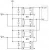
I'm building a simple counter to control 4 Reed Relays. 2 of the relays break 1200Vac and the other 2 break 30Vac. The counter (74LS93) is used With Inverters & NAND gates so that by repeatedly pressing the (debounced) start button, the circuit loops through 5 states; OFF, Relay1 (HV), Relay2 (HV), Relay3 (LV), Relay4 (LV), Reset.

Everything works perfectly... until I turn on the HV supply and then the sequence goes errattic. I thought it could be noise so I moved the relays into a separate earthed metal box but it made no difference

To eliminate any leak-back into the control circuit, the HV Relays have a separate 24V supply and are activated by photocouplers & FETs so this circuit has no electrical connection to the TTL counter circuit.

I'm sure there is something blindingly obvoius I'm missing. any ideas...?

Ta Much
Mike.
 
Have you considered the possibilities that the noise resulted from switching 1200Vac can be carried via the common 240V ac supply line and went into the +5V ouptut? (I'm assuming the 24V power supply and the 5V power supply shares a common 240V line)

In that case enclosing the relays would not help. A LC filter on the AC input of the +5V supply might.

If you can post a line/block diagram of the actual circuit configuration along with the power supplies then you will certainly get more suggestions here.
 
No I hadn't thought of that. I've tried it by powering up the 1200V machine on an Isolated supply and powering the 5V & 24V circuits from bench top PSUs does this cover the filtering angle or do you think I should still try to add a filter?

I've checked the circuit by Oscilloscope and cannot find any noise any where. The only difference is the outputs from the 74ls93 which are erattic with the 1200V on.

I've attached a circuit diagram.
 

Attachments

  • circuit_606.jpg
    circuit_606.jpg
    38.1 KB · Views: 815
I have made some suggestions. see the diagram.

When you said the operation was erratic, did you mean that the LEDs did not change to next correctly according to each press of the GO button?
 

Attachments

  • circuit_606.gif
    circuit_606.gif
    21.9 KB · Views: 783
Your drawing does not show any bypass capacitors across the +5 V supply line. There should be one across each IC as close to the IC as possible.

Also, I would have used CMOS rather than TTL as CMOS has higher noise immunity.

Len
 
Thanks for the help.

Output D from the 74LS93 is not used. I tried with it grounded in case it helped the situation. it didn't.

I have diodes on all the relays, Just never included on the drawing.

I'll try reducing the pull-up resistors to 100 Ohms and let you know.

We have another (more complex) unit which is switching the same 1200V supply and it uses the same relays (Sanyu USM-12724) with no problem (Unfortunately, this unit is cotrolled by a PLC and my budget does not stretch that far hence the logic circuit!!!)

There are no Bypass Capacitors fitted. I will fit some and let you know. What value should they be?

The idea of rebuilding it with CMOS is getting more appealing daily!
 
The 'D' of IC 74LS93 is an output pin. One should never ground an output pin.

The bypass capacitor values are not critical. You can use any ceramic capacitors of 100nF or higher and fit them as close to the the two power pins of each IC as possible.

Your reply answered the comment from jnegowski. The relay you have used is rated at 3KV, 3A with a 24V coil. Mtaylor your circuit diagram showed it as 12V so it is still not exact.

You have not said in the reply what "erratic operation" means. Did the circuit sometimes advances and sometimes not when the GO button is pressed? Or it jumps several steps?
 
The 12V in the diagram is incorrect. I originally used 12V Relays but changed to the 24V and never updated the diagram, sorry.

The erratic operation does not have any constant pattern;
I'm looking for the count 1, 2, 3, 4, Reset. and it works OK but when I add the 1200V. i'm getting; 2,4,2,Rst or 1,1,1,3,2,Rst, or 1,4,Rst, etc... the combinations are endless. Also sometimes it will switch twice for one press of the switch, for example 1-4,2,3,4,Rst with pushing the switch 5 times.

Apologies for the explanation but it's not easy to describe. The outputs of the counter do not run in the correct sequence.
 
mtaylor said:
The 12V in the diagram is incorrect. I originally used 12V Relays but changed to the 24V and never updated the diagram, sorry.

The erratic operation does not have any constant pattern;
I'm looking for the count 1, 2, 3, 4, Reset. and it works OK but when I add the 1200V. i'm getting; 2,4,2,Rst or 1,1,1,3,2,Rst, or 1,4,Rst, etc... the combinations are endless. Also sometimes it will switch twice for one press of the switch, for example 1-4,2,3,4,Rst with pushing the switch 5 times.

Apologies for the explanation but it's not easy to describe. The outputs of the counter do not run in the correct sequence.

This type of erratic behaviour is what I would expect if you do not have bypass capacitors. The high voltage noise would also contribute.

You also need to be careful how you connect the ground connections. High current tracks must be isolated from the logic ground. Connnect them at one point only.

Len
 
OK, I've added the bypass caps (100nF) to all the ICs and it's getting better, there's now not so many errors so it looks like we're nearly there.

Is there anyhting else I can try?


Ta Much
Mike
 
What is the nature of the load that you are switching? Is it highly inductive?

The switching off of the current produces lots of interference and these have found a way into your counter circuit.

You need to find out why such interference can travel into your circuit. Through the air or via the power supply AC connections?

Can you increase the distance between the two? Can you use battery for the counter circuit for testing purposes to isolate the cause?
 
you got few good tips already, you should also add tantal or regular aluminum elcos (10-100uF) in parallel with the 100nF.
what is the NOR gate chip?
how long are wires from gate inputs to switch that clocks circuit?
is the switc mounted on the metal enclosure? check post by ljcox...[/code]
 
At the moment there is no load. the 1200V will eventually be used for measuring lekage current so the current flow will always be very low.

In the drawing, Ry1 is actually a pair of parallel connected relays so that I can break both lines of the 1200V supply. Ry2 is the same. I've attached a drawing of this to clarify it. At the moment, I ave nothing connected to the "Outputs" of the Relays.

The 1200V is completely isolated from the logic circuit. The grounds are not connected together.

The Switch is plastic bodied and fitted to the metal case, the wires are approx 30cm long.

The ICs I've used are;
1 x 74LS 93 (counter)
4 x 74LS20 NANDs (1 x Debounce, 3 x relay selectors)
1 x 74LS04 Inverter
 

Attachments

  • rycircuit.jpg
    rycircuit.jpg
    23.2 KB · Views: 692
mtaylor said:
At the moment there is no load. the 1200V will eventually be used for measuring lekage current so the current flow will always be very low.

If the problem happens at no load, then the situation is even worse than it could be. You are facing problems of capacitive coupling where part of the high voltage is being coupled into the control circuit via stray capacitance.

I can understand this might affect the MOSFET but I don't understand why this coupling can possibly affect your counter circuit to jump several counts when you have no electrical connection between them.

The only way to find out is to use a battery to power the TTL circuit and test again.

Are you willing to build another simplier circuit if this one fails. I can think of a much simplier one using 4017 with 12V power supply that function exactly as yours but is more robust. I'll use two additional relays driven via optocoupler to drive these four high voltage relays and avoid the capacitive coupling problem.
 
Does it work if you disconnect all of the relays?

This would prove whether there is noise from the relays. Also, I don't see any diodes across Rly 3 & 4.

Len
 
I've tried it with the battery to power up the logic circuit only and I get the same result. Everything works great until I power up the 1200V!!!!

The Diodes on Ry3 & 4 are there just not shown on the drawing.

I'm thinking that building another circuit would be a much better way to go. Can you send me the details please?
 
This is my design. I have chosen to have all the coils of the HV relays grounded so that capacitive coupling effect can be minimised. You really have to earth the connection as shown under relay RL1B.

If you like, the two LEDs for RL3 and RL4 can be inserted at the locations of the two "blue dots" if RL3 and RL4 is far away from the control circuit.

If you want a separate RESET push button, you can place one across the 0.22uF capacitor.

Upon power up, the 0.22uF capacitor at the 4017 reset pin would force the chip into reset state and Q0 output goes HIGH. With the GO button is pressed, a clock pulse is sent to the 4017 and it advances with Q1 output goes HIGH. This turns on LED and the optocoupler...etc....When state Q5 reached, the F/F formed by 4001 would generate a reset to the 4017 putting it into Q0 again. So the stable states of the circuit are: Q0-->Q1-->Q2-->Q3-->Q4-->Q5Q0 as the Q5 state is very very short.

Be careful with the common of the supplies so that they do not form earth loops. Please also wait for others viewing this forum to offer their check/improvement before building it.

If you have question about the circuit design, ask here.
 

Attachments

  • hvbin.gif
    hvbin.gif
    21.4 KB · Views: 570
The CMOS version should be much more immune to noise.

However, the reset flip flop is not necessary.

I would simply connect the diode from the Q5 to Rst and remove the FF.

But tie the unused inputs of the NOR to gnd

Len
 
Status
Not open for further replies.

New Articles From Microcontroller Tips

Back
Top