On my previous post I was trying to make a binary clock with LEDs. I decided to rewrite and clean up my code but this time only program it to illuminate the leds that are associated with the hours display(the first 4 LEDs that are to the far left of my display). It seemed that it worked correctly except that when the LED that is to the far left(connected to pin 3) illuminates the two LEDs on the far right (connected to pins 12 an 13) also illuminate. This makes no sense since nowhere in my code do those LEDs illuminate. What is going on?
Thanks in advance
Thanks in advance
Code:
 LIST R=DEC
 INCLUDE "p16f630.inc"
	__config (_INTRC_OSC_NOCLKOUT & _WDT_OFF & _PWRTE_OFF & _MCLRE_OFF & _CP_OFF )
	ERRORLEVEL -224        ;remove tris message

 CBLOCK 0x020                ;  Variable Declaration
	DlayValue:2                  ;  Requires 24 Bit Counter (w/ WREG)
 	minutes
	hours
	int13
	int60
 ENDC

	;Set all ports to output
	movlw B'00000000'    ; all bits low in W
	tris PORTA           ; contents of W copied to PORT A ...
	tris PORTC           ; and PORT B

	;set time variable
	movlw d'12' ;hours cant start at zero, start time at 12'oclock
	movwf hours

	movlw 0x00
	movlw minutes ;start minutes at zero

	;set general variable
	movlw d'13'
	movwf int13

	movlw d'60'
	movwf int60

	;set display
	movlw 0xFF		;all lights off
    movwf PORTA
    movwf PORTC

;////////////////////////////////////////Delay MACRO/////////////////////////Created by:Myke Predko/////////////////////////////////
Dlay Macro Cycles
 variable CyclesLeft            ;  Keep Track of Remaining Cycles
 variable LargeNum
CyclesLeft = Cycles
 local LongLoop
 if Cycles > 0x04FFFF00         ;  Can't Handle the Anything > 83 Seconds (@ 4 MHz)
 error "Required Delay is longer than 'Dlay' Macro can support"
 endif
 if Cycles > 327681             ;  Need Large Loop?
LargeNum = CyclesLeft / 327681
  movlw   LargeNum
  movwf   DlayValue + 2         ;  Calculate Number of Loops
LongLoop:                       ;  Repeat for Each Loop
  clrf    DlayValue + 1         ;  Do Maximum Possible Loop Count
  clrf    DlayValue
  decf    DlayValue, f
  btfsc   STATUS, Z
   decfsz DlayValue + 1, f
    goto  $ - 3
  decfsz  DlayValue + 2, f      ;  Repeat Loop
   goto   LongLoop
CyclesLeft = CyclesLeft - ((LargeNum * 327681) + 1 + (LargeNum * 3))
 endif  ;  Need Large Loop
 if Cycles > 14                 ;  Will a Loop be required?
  movlw   high (((CyclesLeft - 3) / 5) + 256)
  movwf   DlayValue + 1
  movlw   low (((CyclesLeft - 3)/ 5) + 256)
  movwf   DlayValue
  decf    DlayValue, f          ;  5 Cycle Constant Delay Loop
  btfsc   STATUS, Z
   decfsz DlayValue + 1, f
    goto  $ - 3
CyclesLeft = CyclesLeft - (3 + (5 * ((CyclesLeft - 3)/ 5)))
 endif                          ;  Finished with Loop Code
 while CyclesLeft >= 2          ;  Put in 2 Instruction Cycle Delays
  goto    $ + 1
CyclesLeft = CyclesLeft - 2
 endw
 if CyclesLeft == 1             ;  Put in the Last Required Cycle
  nop
 endif
 endm
;///////////////////////////////////End of Delay MACRO//////////////////////////////////////////////////////////

;////////////////////  By Luke BrownGold


START

	;check to see if hours have reached 13
	movf    int13, w               ;  if hours >= int13 then resetHours
	subwf   hours, w
	btfsc   STATUS, C
	goto   resetHours	;reset hours will return us back to start

	;check to see if minutes have reached 60
	movf    int60, w               ;  if minutes >= int60 then resetMinutes
	subwf   minutes, w
	btfsc   STATUS, C
	goto   resetMinutes  ;reset hours will return us back to start

	;display the time

	;clear display
    movlw 0xFF
    movwf PORTA
    movwf PORTC

;/////////////////-------------HOURS LEDS
	BTFSC hours,d'3' ;    is bit set
    BCF PORTA,d'4' ;      yes, so illuminate LED

	BTFSC hours,d'2'
    BCF PORTC,d'5'

	BTFSC hours,d'1' ;    is bit set
    BCF PORTC,d'4' ;      yes, so illuminate LED

	BTFSC hours,d'0'
    BCF PORTC,d'3'

	;delay
	Dlay 100000  ;  Delay 0.1s, will make longer(shorter for testin purposes

	;increment minutes
	incf minutes,d'1'

	goto START
;-----------------------------------------------------------------------;
;                       	Reset the hours varialbe                    ;
;-----------------------------------------------------------------------;
resetHours
	movlw d'1'
	movwf hours

	movlw d'13'		;just incase var int13 get reset by equals method
	movwf int13
 goto START

;-----------------------------------------------------------------------;
;                       	Reset the hours varialbe                    ;
;-----------------------------------------------------------------------;
resetMinutes
	movlw 0x00
	movwf minutes

	incf hours, d'1'	;increment the hours by one

	movlw d'60'		;just incase var int60 get reset by equals method
	movwf int60
 goto START

;-----------------------------------------------------------------------;
;                        Delay for ten seconds                          ;
;-----------------------------------------------------------------------;
tenSec:
	Call oneSec
	Call oneSec
	Call oneSec
	Call oneSec
	Call oneSec
	Call oneSec
	Call oneSec
	Call oneSec
	Call oneSec
	Call oneSec
 return
;-----------------------------------------------------------------------;
;                        Delay for one second                           ;
;-----------------------------------------------------------------------;
oneSec:
	Dlay 100000                 ;  Delay 0.1s
	Dlay 100000                 ;  Delay 0.1s
	Dlay 100000                 ;  Delay 0.1s
	Dlay 100000                 ;  Delay 0.1s
	Dlay 100000                 ;  Delay 0.1s
	Dlay 100000                 ;  Delay 0.1s
	Dlay 100000                 ;  Delay 0.1s
	Dlay 100000                 ;  Delay 0.1s
	Dlay 100000                 ;  Delay 0.1s
	Dlay 100000                 ;  Delay 0.1s
	nop
	nop
	nop
	nop
	nop
	nop
	nop
	nop
	nop
	nop
 return


 end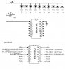
 ic16f630) and the same problem continues.
