Continue to Site

Welcome to our site!

Electro Tech is an online community (with over 170,000 members) who enjoy talking about and building electronic circuits, projects and gadgets. To participate you need to register. Registration is free. Click here to register now.

  • Welcome to our site! Electro Tech is an online community (with over 170,000 members) who enjoy talking about and building electronic circuits, projects and gadgets. To participate you need to register. Registration is free. Click here to register now.

bidirectional 9v DC motor controller

Status
Not open for further replies.

chaminda

New Member
I'm a complete newbie to electronics so need a lot of help

I want to control a car DVD player screen - its a motorised screen which slides out (see pic).
Its run by a 9v motor (ff-180sh-14240)> not sure of the current it drags. Tested it with a 9v battery and works fine


So what I want to do is:
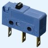
There are 2 switches (microswitch) to detect when the screen is its neutral position (i,e fully verticall) and one when it fully folded out.

1. There one button to control the screen i.e motor.
initially the screen is in its neutral position i,e fully vertical
2. If i press it for a short period of time the screen moved a bit out (i.e the motor rotates a small amount). I can repeat this till i get the screen to a position i like or maximum open position
or If I hold down the same button for a longer period of time (lets say 3 seconds) the screen slides out to its fully open position.
4. This position is detected by a microswitch which switches on. This allows the motor to move in the reverse direction when the button is pressed again -->
4. While in the position if i press the button again the screen moves back completely to its vertical (neutral) position.i.e the motor moves in reverse. It know its at the neutral position as it switches on a different switch


heres a pic of the screen positions.


I was thinking of doing this using relays (time delay relay, Polarity conversion circuit etc).
I just need to detect when the screen is fully out and fully in so i can stop the motor and reverse the motor on the next button push. Was thinking of using micro switched

I was hoping someone can help me do up a circuit preferably using relays or if not some sort of IC.
Please help me!
 

Attachments

  • Untitled.jpg
    Untitled.jpg
    43.6 KB · Views: 335
Hi chaminda,

welcome to the forum.

Here is a simple circuit suiting your needs.

Nothing can go wrong using relays and limit switches as drawn regardless of the switch position.

Limit switches are micro switches as shown in the attachment.

If the switch is in the "open" position the motor will rotate until the limit switch interrupts the ground path. Simultaneously the "open" LED will be lit. The same will happen in the "close" position with "shut" LED lit.

Since an SPDT switch is used you should avoid reversing the motor while your device is moving. Reversing the motor at full speed results in a momentary stall with high current flow.

You are welcome to obtain the Eagle files via email PMing me your full name and email address.

Boncuk
 

Attachments

  • OPEN-CLOSE-RELAY-SCH.gif
    OPEN-CLOSE-RELAY-SCH.gif
    14.9 KB · Views: 331
  • OPEN-CLOSE-RELAY-BRD.gif
    OPEN-CLOSE-RELAY-BRD.gif
    23.4 KB · Views: 242
  • MA1050_1.jpg
    MA1050_1.jpg
    12.3 KB · Views: 202
Last edited:
thanks

Hi thanks for the quick reply
I'm a complete newbie and haven't done electronics for a long time
I'm struggling to understand the circuit.
As mentioned earlier i''d like to control it with a single switch, for the motor to go both ways and when going the reverse way for it to completly go back to its vertical (neutral)
position. I've uploaded a pic of how it works

Could you please explain the circuit a bit more. struggling to understand how the motor reverses and also how it would completely go back to the neutral position from fully open when the switch is pressed.
Sorry about all the questions ! I'm actually a doctor so haven't done much work in this field
thanks
 

Attachments

  • Untitled.jpg
    Untitled.jpg
    43.6 KB · Views: 186
Hi
I sort of understand how its reversing. Whats K1 and K2 if i'm using a SPDT switch? Also this seems to be a 2 switch porcess as s1 has ?2 positions - not a simple push switch
Also i'm trying to move a 9v motor - not sure if this is suited for 9v motors

thanks
 
change of plan

Hi
I've been thinking of this project and decided to change the plan to a much simpler solution
this time I'll have 3 button
one moves the motor one way (i.e slides the screen down) a bit every time you press it. This can be done till the horizontal position is reached
The other moves it the other way (i.e slides the screen) a bit every time you press it. This can be done till the full vertical position is reached

Now the 3rd button is more complicated.
If pressed once it'll fully slide the screen out. If pressed again it'll slide it fully in. This will the tricky one. I was thinking of something like a latch relay
All these could be wired to the same limit button through some diodes so it doesn't short circuit each other.
Need some help with the 3rd button ?need a latch relay or similar circuit

thanks
 
Just to add
Will still need to be a 9v circuit as my motor is 9v - i can do with some help choosing a relay and designing a simple circuit to accommodate my 3rd button.

the plan is to do a dc dc stepdown from 12v to 9v (since its in the car) and feed that to the circuit so the motor gets 9v in the end. (although through a relay this may drop down a bit)
The motor i'm using is ff-180sh-14240 theres some info on that type of motor in the web
thanks
 
no more change of plan please

Hi chaminda,

I changed the design according to your desire.

Here is the result. BCB size is 3.3740X3.6375".

The circuit has not been tested!

Use adequate filtering when using the circuit in your car. Car alternators provide pretty "dirty" DC!

Boncuk

P.S. The second layout is revised for a smaller board, now measuring 3.4750X3.2125"
 

Attachments

  • OPEN-CLOSE-RELAY-I-SCH.gif
    OPEN-CLOSE-RELAY-I-SCH.gif
    28.4 KB · Views: 293
  • OPEN-CLOSE-RELAY-I-BRD.gif
    OPEN-CLOSE-RELAY-I-BRD.gif
    24.1 KB · Views: 212
  • OPEN-CLOSE-RELAY-II-BRD.gif
    OPEN-CLOSE-RELAY-II-BRD.gif
    27.2 KB · Views: 203
Last edited:
Hi
thanks so much for the circuit. looks quite complicated.
I was thinking of doing it with a DPDT relay for the 3rd button (i.e the one that opens the screen fully and folds it fully)
the other two buttons could be just simple switches.
The power input would go through a 12v to 9v converter
will try to draw up a diagram tomorrow
thanks
 
Thinking and have others think!

Hi chaminda,

how do you "tell" a relay to close contacts for a certain operation and deactivate it with a single switch?

The solution I offered is error free (after revision) and requires push buttons only.

You have all choices you wanted:

Open and close fully when pushing one button alternating, open and close partly pushing one of two more buttons.

I guess you haven't made up your mind about what you really want.

Furthermore I haven't stolen my time to help somebody who can't decide what he wants.

Conclusion: I'm out of the game!

Boncuk
 

Attachments

  • OPEN-CLOSE-RELAY-I-BRD.gif
    OPEN-CLOSE-RELAY-I-BRD.gif
    29.2 KB · Views: 180
  • OPEN-CLOSE-RELAY-I-SCH.gif
    OPEN-CLOSE-RELAY-I-SCH.gif
    28.5 KB · Views: 198
Last edited:
Status
Not open for further replies.

Latest threads

New Articles From Microcontroller Tips

Back
Top