Continue to Site

Welcome to our site!

Electro Tech is an online community (with over 170,000 members) who enjoy talking about and building electronic circuits, projects and gadgets. To participate you need to register. Registration is free. Click here to register now.

  • Welcome to our site! Electro Tech is an online community (with over 170,000 members) who enjoy talking about and building electronic circuits, projects and gadgets. To participate you need to register. Registration is free. Click here to register now.

Bi-directional Amplifying Component?

Status
Not open for further replies.

DigiTan

New Member
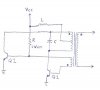
Previously in this circuit, I noticed the value R had a direct impact on the overall Vout/Vcc gain of the circuit. Problem is: the R resistance needs to be electronically adjustable and I can't find digital potentiometers with 2 Watt ratings.

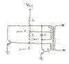
I thought of adding a BJT in parallel with the resistor. The problem is there's an AC signal on the resistor (24Vpp) that's capable of destroying a bipolar transistor. I heard JFETs may be a better option for controlling a bi-directional signal. Would a parallel JFET help scale this bi-directional current through the resistor?
 

Attachments

  • r_problem.jpg
    r_problem.jpg
    12.7 KB · Views: 193
Hello,

You should really check the design to make sure that the base emitter of either of the transistors does not go too far negative. It sounds like one ore more transistors might be getting too high of a reverse BE drive. If that is the case that would have to be fixed first or else move to another design.

You really have to be careful how you change that resistor anyway, if you do at all. Going too high in value may prevent one or both of the transistors to not be able to enter saturation fully and that could cause overheating.

Another possibility for control is to PWM the bases of the two transistors rather than drive with that base winding.
You'll have to try this of course and look for voltage spikes too.

Another option may be to simply PWM the supply voltage, Vcc, with some filtering to average the voltage out. The Vcc getting to the resistor that is, not for the entire circuit power. The frequency should be higher than the normal circuit oscillation unless the load can tolerate a lower frequency and then it can be lower than the circuit operation perhaps.

Alternately, PWM the Vcc for the entire circuit, using some filtering also.
 
Last edited:
The existing transistors are doing okay. Their Vbe and Vce signals never reverse and they only see about 15% of their max current rating. The first diagram had a minor error in it where inductor L was shown in its old location.

I have an adjustable buck converter that can scale the input voltage, but to keep overall efficiency as high as possible I want to try varying the resistance seen between nodes A and B. I heard the gate and source pins of certain JFET model are interchangeble, but I wasn't sure if that actually means they can handle true AC. If it is, then I want to have one share current with resistor R.
 

Attachments

  • r_problem_corrected.jpg
    r_problem_corrected.jpg
    15.1 KB · Views: 158
Last edited:
Im not sure what you would use to change that R value.

You can make any device bi directional by using a bridge rectifier if your circuit can tolerate the voltage drop of two diodes, but you need a common point to reference the control signal unless maybe you use an opto isolator in conjunction with a transistor with bridge rectifier. Does this sound reasonable to you? If so i'll post details.
Actually it's not that complicated:
Connect opto (transistor output) to transistor, connect bridge rectifier DC side to transistor, connect AC side of bridge rectifier to current resistor terminals, make current resistor higher in value. As the opto is activated, it activates the transistor, the transistor shorts out the bridge with some resistance value, the bridge presents an AC resistance to the circuit just as it is now. You should still keep R in the circuit, just make it high enough to allow it to work in the circuit if the transistor connected to the opto turns off completely.
 

Attachments

  • AC-ResistorController-01.gif
    AC-ResistorController-01.gif
    10.8 KB · Views: 157
Last edited:
Status
Not open for further replies.

Latest threads

Back
Top