Electro Tech is an online community (with over 170,000 members) who enjoy talking about and building electronic circuits, projects and gadgets. To participate you need to register. Registration is free. Click here to register now.
Welcome to our site! Electro Tech is an online community (with over 170,000 members) who enjoy talking about and building electronic circuits, projects and gadgets. To participate you need to register. Registration is free. Click here to register now.
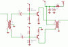
OK, let me do a schematic. I thought a Push-Pull was a Push-Pull. But let me make the schematic. Obviously Nigel has no idea what one looks like. He's good at critisizing but I haven't seen any schematics of anything he makes. You Nigel. You!
Man, My receiver will pull a QRP signal out of BCI everywhere and the transmitter already goes a good 800 miles on two watts. So bash away. I want to see some of your stuff. Oh, maybe he can karate chop a circuit board and make it work.
OK I through this together real quick. I got to run back out again.
I just want an answer to see if it will save me time.
I know you can do both the bias and RE but which is quickest or do I need to do both? See, I know that you can even used un-matched pair with power transistors by using adjustable voltage regulators. I've seen it done.
This site uses cookies to help personalise content, tailor your experience and to keep you logged in if you register.
By continuing to use this site, you are consenting to our use of cookies.