Continue to Site

Welcome to our site!

Electro Tech is an online community (with over 170,000 members) who enjoy talking about and building electronic circuits, projects and gadgets. To participate you need to register. Registration is free. Click here to register now.

  • Welcome to our site! Electro Tech is an online community (with over 170,000 members) who enjoy talking about and building electronic circuits, projects and gadgets. To participate you need to register. Registration is free. Click here to register now.

Beam alarm system

Status
Not open for further replies.

zachtheterrible

Active Member
Hi everyone. i have an assignment to give a 10 min speech on a job that i would like to have in the future for school. of course im gonna give it on being an electronics engineer :lol: . so i got the idea to design and build a little beam alarm system so i can show the steps, calculations, etc., some of the things that would be involved in being an EE.

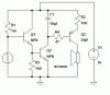
here is the circuit that i have designed. The voltage divider part works. And the delay for the buzzer to stay on for a couple seconds also works. I tested both of those parts seperately.

It doesn't work though. Where am I going wrong? and please don't point me to another circuit, remember, i'm trying to design this myself :lol: thank you very much!
 

Attachments

  • beam_alarm.gif
    beam_alarm.gif
    5.2 KB · Views: 891
Q3 emitter and collector is drawn reversed; emitter must be to +ve side

Resitor values R3,4 seems very low?
 
Q3 emitter and collector is drawn reversed; emitter must be to +ve side
:oops: :oops:

I tried uploading a new version, but i cant seem to. just imagine the emitter is @ +ve side.
 
Give your description of how you see this should work and then we can look at your reasoning and help by giving pointers. This way you will understand your mistakes better, and you can truly say you have designed this yourself :D

WOW, I see I am promoted to Master :shock:
 
oh, yeah, i guess i shouldve explained it better.

wel, basically, a light (IR, laser, wutever) is sensed by the photoresistor. Everything to the left of Q2 forms a voltage divider so that Q1 is on when there is no light on the photoresistor (the beam is broken). This turns Q2 on. C1 charges through Q2. When Q2 turns off (beam is restored) C1 drains itself through R4, Q2, and R2, which makes the buzzer stay on a couple seconds. Anyways, thats the way it is supposed to work.

WOW, I see I am promoted to Master
Look @ me, i'm an oracle. HAA! 300 more posts and ill be a god! HAA HAA HAA!!! i guess i just blab too much :lol:
 
Q3 is correctly wired for a PNP transistor. Your problem is probably due to the choice of values for R2 and R4. With your values the buzzer only gets about 3V.

Transfer R2 to the collector circuit of Q3 if you need it to limit current - if it's a piezo buzzer then leave it out altogether. Increase R4 to 4K7 for starters. That should get you enough drive for the buzzer.
 
If Q1 ever manage to switch on hard enough (accidents happen), Q2 will be fried because of high base current into Q2. Good practice will be to limit base current to Q2 in the collector of Q1 with a resistor. Maybe move R3 to Q1 collector
 
Thank you very much everyone! this is sweet, im designing my own circuit :lol:

Theone, when you say to move R3 to the collector of Q1, wouldn't that result in Q2 not turning on @ all? Because the base would be seeing much more negative than positive.

Nigel, i like your idea of using 4k7 for R3. This would help Q2 turn on better, right? i imagine that this is where my problem is in getting the alarm delay part of my circuit to turn on.

Pebe, i will transfer R2, good idea :lol: . upping R4 to 4k7 will result in a longer buzzer delay, right? Would you be able to give me an explanation of how you figured that my buzzer would be getting 3 volts? I know how to calculate the current (ohms law), but i have yet to figure out how to find the voltage that components are getting.
 
Yes, using 4K7 for R4 will change the delay.

As for the 3v, I started from the assumption that Q2 would be switched on hard and its collector would be approximately 0v.

R4, the BE junction of Q3, and R2 then form a potential divider across the 9v supply. Leave the buzzer disconnected for the moment. Now with no collector current flowing, Ohms law says that the emitter voltage will fall to approximately 3v. Now connect the buzzer. The collector cannot rise above the emitter so it, too, will be 3v. With the loading of the buzzer it will be even lower.

That said, Nigel pointed out that R3 was too low and Q2 could not switch on. Let’s look at that part of your circuit and see why. The maximum current in Q2 is when your sensor is open circuit. Then there is a path through R1 and the bases of Q1 and Q2 which gives 9v-2*0.6v (=7.8v) across R1. That gives a base current of 7.8uA. Assuming a Q1 gain of 100 will give the emitter current as 0.78mA. This flowing through R3 will give .078v across it which is not enough to turn on Q2.

R3 should be chosen so that the voltage drop across it would be above and below 0.6v for the two respective states of the sensor, so that Q2 is switched on or off
 
Thanx pebe
Now with no collector current flowing, Ohms law says that the emitter voltage will fall to approximately 3v

ive been wondering this for quite some time. how do i calculate how much voltage a resistor drops?
 
The voltage dropped by a resistor increases with current and increases with the resistance. Hence Ohms law that states V (voltage) = I (current) x R (resistance). In your case the BE junction of Q3 is a fixed value (approx 0.7v) and so this can be subtracted from the source voltage (9v) for the purposes of the calculation.

So we have 8.3v (9v - 0.6v) dropped across 100ohms + 47 ohms = 147 ohms. Manipulating Ohms law also gives I = V/R. So the current through R4 and R2 = 8.3/147 = ~0.056A = 56mA

Coming back to using the formula V = I x R, gives the voltage across R2 as .056 x 100 = 5.6v. So the buzzer voltage will be 3.4v In reality, there would also be the buzzer current through R2 which would increase its voltage drop.
 
thank you so much pebe, that makes so much sense :D . ive been wondering how to do that for quite a while.
 
hi again. ive built and revised the alarm (see picture) and got it working exactly the way i wanted it to, accept for one problem.

when it works the way i want it to, the buzzer stays on for precisely 9 seconds and then fully shuts off. sometimes though, the buzzer will shut off after 9 seconds, and then a couple seconds later, start buzzing again for another 20 sec or so, but very quietly, then shut off. and sometimes, right after the 9 second delay, the buzzer will audibly get much quieter, but stay on and get quieter and quieter until it shuts off, again, for about 20 seconds.

Fully discharging C1 by a piece of metal over the leads fixes this problem. I cannot find any recognizable pattern such as it does this after the 10th time, or when i trip it a couple times very close together. it makes no sense. HELP!!

EDIT: woops, i forgot to attach +9v to the circuit :oops: :roll:
 

Attachments

  • beam_alarm_172.gif
    beam_alarm_172.gif
    7.9 KB · Views: 665
If your circuit is drawn correctly, then Q3 is wrongly wired. It is a PNP transistor so its collector must be -ve with respect to its emitter. You could conveniently connect its collector to Q4 emitter but I'm not sure that will give the polarity of the switching you want.

When the LDR goes high-resistance should that give alarm on or alarm off?
 
im sorry, i forgot to change the transistor's orientation. in swcad iii, which is what i used to make the schematic, for some reason, when u place a pnp transistor, it puts it like that. last time i fixed it in paint, but this time i forgot.

You could conveniently connect its collector to Q4 emitter but I'm not sure that will give the polarity of the switching you want.
im not sure what you mean by this. could u explain a littl more?

When the alarm goes high resistance (beam is broken) the alarm goes off.
 
I can try explain your problem with the aid of a few circuits. I am substituting the NPN with a switch for simplicity.

Buzz_on is your circuit working just after the NPN switched on, charging the cap. Note the current to the buzzer and the voltage over the buzzer. So far looks OK.

Buzz_Bad is your circuit after the NPN already turned off (for 9 sec) creating an almost open circuit. I have put 50M Ohm over the switch to simulate the transistor turned off. Notice that there is still some current going to the buzzer and some low voltage over the buzzer.

Buzz_good is the modified circuit with the 1M resistor added to the base of the PNP. It shows the conditions again after about 9 seconds from the NPN turning off, BUT see how in this instance the current is zero, voltage over buzzer is zero and the voltage over the cap is under 0.6v.

Now your circuit failed because in your circuit the cap could not fully discharge (or low enough) through the base-emitter junction of the PNP and the leakage resistance 50M from the NPN still kept a very small current flowing, helping the PNP to stay on (slightly) and also work against the discharge of the cap to some degree.

In the working circuit the 1Meg resistor helps to discharge the cap once the b-e junction stopped conducting. Also the value of this resistor is such that the cap is discharged faster than the leakage current from the NPN can charge it up again.

Hope you followed all that :D
 

Attachments

  • buzz_good.gif
    buzz_good.gif
    8.5 KB · Views: 528
  • buzz_bad.gif
    buzz_bad.gif
    8.2 KB · Views: 511
  • buzz_on.gif
    buzz_on.gif
    8.3 KB · Views: 524
thanx theone, that worked quite nicely. thanx for taking the time to make me the pictures and everything, really appreciate it

i was thinking of putting a resistor there to drain the cap but i wasnt sure wut value. i shouldve just aked that :lol:
 
I thought it would aid in showing not only you, but other learners how a simple circuit can be very interesting once you start analyzing it.

Happy learning! :wink:
 
just wen i think im done . . . well, terrible's law has been proven true once again (down in my signature). i just build a PCB for the circuit today and of course it doesn't work.

the buzzer stays on all the time no matter wut. the very very strange thing is that in the part of the circuit wher the base of Q1, the LDR and R1 meet, i am getting around 10v!! the 10v because i am using a walwart supply and it puts out 10. but on a simulation that i ran, it should only be about 1.6v @ the highest!! i replaced Q1, didnt do nothin, n i know foresure the LDR is okay. wut could be causing this?
 
Status
Not open for further replies.

Latest threads

New Articles From Microcontroller Tips

Back
Top