Continue to Site

Welcome to our site!

Electro Tech is an online community (with over 170,000 members) who enjoy talking about and building electronic circuits, projects and gadgets. To participate you need to register. Registration is free. Click here to register now.

  • Welcome to our site! Electro Tech is an online community (with over 170,000 members) who enjoy talking about and building electronic circuits, projects and gadgets. To participate you need to register. Registration is free. Click here to register now.

Battery Charger Design

Status
Not open for further replies.

Frosty_47

New Member
Hello Everyone!

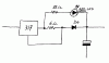
I am trying to design a 14.5V Battery Charger with 200mA current limit. I have no need for Variable Voltage or Current adjustments (just simple design for 1 type of battery I have). I already designed this circuit using LM317. Some one please tell me if this circuit will work for this use...

**broken link removed**


Circuit Notes: The first LM317 with R1 is there to limit the current to 200mA (1.25V/6=200mA).
The second LM317 is for voltage regulation [1.25x(1+10.6k\1k)=14.5V].


Question #1: Is 20VAC input enough? Should I use 24VAC instead (more HEAT) ?

Question #2: When choosing CAP 1 Voltage, should my orientation be based on Vp or RMS?

Thanks !
 
Last edited:
hi frosty,
Looked thru your circuit, its over elaborate for a charger/current limited.
 
Last edited:
Hi frosty,

You should reduce R2 and R3 at least by a factor four.
A good value for R2 is 220 :eek:hm: to 240 :eek:hm: , then calculate R3.
There shouldn't be any problem if the battery ( or a load ) is
permanently connected, but when no load is present the output
voltage will rise well above the calculated value because you forgot
that the LM317 also needs current to function and there isn't a
direct path to ground. They usually solve this problem by taking
lower resistance values for the voltage divider. You can also solve
this problem by connecting a small permanent load like a led and
it's series resistor. 5 mA through the led is enough to solve this
problem.
You also forgot that each battery charger needs to have a reverse
blocking diode in case the mains runs out of power when you're
charging a battery. :D
The 2200 µF capacitor will charge up to the peak value.

on1aag.
 
Last edited:
I would even consider setting R2 to <120:eek:hm: the circuit in the datasheet is for an LM217 which requires 240:eek:hm: to work properly, the LM317 requires 120:eek:hm:
 
Most power supply circuits, including chargers, I have come across have the voltage regulator first then followed by the current limiter. Don't know if that is a technical requirement but I would research that a little if you can.

Others comments on that?

Lefty
 
Thanks for the HELP !

Ayt, I updated the design.

**broken link removed**

I still plan to use a 2200 uF Cap because I have it laying around :D

Changes to previous circuit:

Put in D5-D6 to protect the charger from reverse current when it is off and still connected to battery. Replaced R2 with 240 Ohm because thats what the datasheet for LM317 recommends. R3 was also reduced to 2.8k [1.25x(1+R3/R2)-(1.4V drop due to D5&D6) =14.5V]. Increased the Input Voltage to 24Vac due to transformer availability. Added RL for LED to eliminate no current operation. One thing still not clear to me...

Should my CAP voltage be based on Vp or RMS when dealing with AC ?

Thanks a lot for all your HELP!!!
 
Hi Frosty,

When you changed the values of the resistor divider network
of the LM317, the extra load with the led was no longer necessary.
These resistors load the regulator as well, that's the reason why
they select those low resistance values for it. But you should keep
the led in the circuit, it's always handy when you can see wether it's
working or not.
You should remove D6, one diode is enough.
Keep us informed of your progress.

on1aag.
 
Ayt thanks a lot for your help on1aag !

I will still keep RL because I need it for the LED. Removing D6 will make very little difference because the diodes come in packages of six at the place where I buy em, so might as well keep D6 for that extra protection :D.

I had one question rise up before me during all this, how do I hook up an LED that will be on during Load/charging operation ?

Thanks again !


BY THE WAY, BLIZZARD HAS ANOUNCED STARCRAFT 2 IN DEVELOPMENT !!!
 
Last edited:
Battery charger indicator.

Hi Frosty,

Maybe there is a way to put D6 to good use.
The voltage drop accross R1 is 1,25 volts when charging.
That is a little too low to light a led, but if you put the
useless D6 in series with this resistor the total voltage drop
will be close to 2 volts and that is enough to light a led.
The 22 :eek:hm: resistor was calculated for a 10 mA current
through the led, but this might vary slightly because the
voltage drop accross a red led varies from 1,6 to 1,8 volts.
So check it out and adapt the value of the 22 :eek:hm: resistor
to let the led light as bright as the other one.

on1aag.
 

Attachments

  • Battery charger indicator.GIF
    Battery charger indicator.GIF
    6.8 KB · Views: 236
:d:d:d:d:d

I updated the circuit.

**broken link removed**

Thank you very much for all your assistance in this design. I will go ahead and start building this circuit on Tuesday. I still have to design the PCB layout for this circuit using Eagle (that might take a while), so hopefully I will have it working by Wednesday.
Anyhow, I will post the results as soon as I can...


Thank you every one for your time, interest and suggestions !!!-!!! :)
 
Leftyretro said:
Most power supply circuits, including chargers, I have come across have the voltage regulator first then followed by the current limiter. Don't know if that is a technical requirement but I would research that a little if you can.

Others comments on that?

Lefty

Thats correct.But I think he is using this charger for SLA batteries.so no need such a smooth current.
 
bananasiong said:
Isn't it 120 :eek:hm: recommended for LM317?
Yes it is because its max operating current is 10mA which conducts through the resistor. If the resistor is higher than 125 ohms then the output voltage would rise if there is no load if the LM317 has a 10mA operating current.
The datasheet shows a more expensive LM117 using a 240 ohm resistor because its max operating current is lower, it is only 5mA.

But in this circuit, the LED adds enough load so that a 240 ohm resistor is fine.

I calculate an output voltage of 15.1V which is too high for a lead-acid battery. If the 2800 ohm (odd value) resistor is changed to a 2700 ohm standard value then the voltage will be 14.6v.
 
Thank you audioguru !

You are right about the Vout=15.1V

I forgot to recalculate R2 after I moved D6 which used to drop additional 0.7V making the output 14.5V. Anyways thanks for pointing that out! I will replace R4 with 2.7K.

As for current control, it makes very little difference whether you put it before or after the voltage regulator because the voltage regulator itself will smooth out the current so theoretically there shouldn’t be any difference…Anyhow, I will be testing my circuit before building it, and I will try test both scenarios to see if there is any difference in the output current/voltage. But I can only do that on Tuesday because that’s when I have access to one of the Labs in school :D. I will post the experiment results as soon as I can.

Thank you for your interest, time and suggestions!
 
Frosty_47 said:
I just looked through two datasheets for LM317T and both provide multiple examples where R1=240Ω.
Look again. National Semi invented the LM117/LM317. Their datasheet shows multiple examples where R1=240Ω for the more expensive LM117 that has half the max operating current of a cheaper LM317.

In their datasheet, National explains, "If there is insufficient load on the output then the output voltage will rise". The 120 ohm resistor provides a load current of 10.4mA for the LM317 which is higher than its operating current of 10.0mA so that the output voltage will not rise if there is no other load.

But the max operating current occurs at it max differential voltage of 40V and is lower at lower differential voltages.
 
You also asked if 20VAC is enough. Yes it is. 20VAC will provide about 28VDC on the input of the first regulator. The circuit will be dissipating about 2.7 watts overall.

24VAC is probably too much, because you'll have about 33VDC at the input. The circuit will be dissipating almost 4 watts.
 
Actually a 15 V transformer is good enough isn't it? So you will have 21.21 peak. After filtering say 20 V left. Voltage drop of 1.4 V for 2 diodes, 18.6 V left. This is still enough for LM317 to dropout.
For me, the size of the transformer is an issue.

*Just to reconfirm, is 200 mA limited in this circuit?

Thanks
 
As for current control, it makes very little difference whether you put it before or after the voltage regulator because the voltage regulator itself will smooth out the current
The current limit needs to be before the voltage regulator.

If the voltage regulator is first, it'll have a set voltage out and the current regulator will take its own overhead. You'll never get the set voltage.
 
Status
Not open for further replies.

Latest threads

Back
Top