Electro Tech is an online community (with over 170,000 members) who enjoy talking about and building electronic circuits, projects and gadgets. To participate you need to register. Registration is free. Click here to register now.
Welcome to our site! Electro Tech is an online community (with over 170,000 members) who enjoy talking about and building electronic circuits, projects and gadgets. To participate you need to register. Registration is free. Click here to register now.
An OP amp basically takes two voltages and multiplies them by a BIG number (open loop gain). If the noon-invering input is A and the inverting B, then the output is (A-B)G where G is a big number.
Another way of looking at this is that with negative feedback, the A and B terminals will try to be the same voltage. So, in order for A and B to be the same, A must equal B.
These concepts can easily help you understand an inverting amplifier as well.
When positive terminal is higher (always in terms of voltages), the output will rise until it reach a voltage close to positive voltage terminal. And opposite happends when polarity on input changes. This goes very fast, but let's say it doesn't (more easy to explain then).
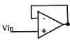
When connected as this, let's assume time t0, the moment you switch on power.
Let's assume there is always 2V on positive terminal, regardless if power is on or not (just to make it easier).
There is many different opamps models, so we also need to assume that output voltage is zeero the moment after power is applied to circuit (in real life it can be everything).
Power is on and situation is that negative input follows output, always. This is now 0V (assumption).
Positive terminal is 2V, wich is higher. Therefore the output rises.
When output reach the same voltage as positive input, the speed of the voltage rise slow down.
But because of delays, output voltage will swing a little bit above positive input voltage.
Now, the opamp detects that negative input (remember: still connected to output) is slightly higher, so the output start decreasing voltage.
And the swinging will continue until it sets at same voltage as on positive input.
This site uses cookies to help personalise content, tailor your experience and to keep you logged in if you register.
By continuing to use this site, you are consenting to our use of cookies.

")