Continue to Site

Welcome to our site!

Electro Tech is an online community (with over 170,000 members) who enjoy talking about and building electronic circuits, projects and gadgets. To participate you need to register. Registration is free. Click here to register now.

  • Welcome to our site! Electro Tech is an online community (with over 170,000 members) who enjoy talking about and building electronic circuits, projects and gadgets. To participate you need to register. Registration is free. Click here to register now.

Balun problem..

Status
Not open for further replies.

sohaib_a

New Member
I have a zigbee transceviver IC...model no. MC13192.I have to connect an antenna to this but the impedance matching is proving to be difficult..maybe because i have never done it before.I hope u guys can help me out.
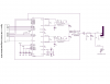
The antenna has to have a 50ohm input imepdance...i got an example schematic from the transceiver datasheet but i am having a problem with the balun specifed (LDB212G4020C-001) because it's too small for me to work with on a breadboard(all the dimensions are in millimeters).So i need to know if there is could be alternative method..maybe i could do the coupling with discrete components?..or is there any other type of compatible balun available..i did search alot though.
Your help will be appreciated..
 

Attachments

  • mc19123.png
    mc19123.png
    53.6 KB · Views: 209
Last edited:
What I gather from the data sheet on the MC13192 is that it is a tranceiver for the 2.4Ghz range, and as a result the circuit would not work on a proto board.
 
Layout at 100MHz is crucial, at 2.4GHz it's absolutely critical, you need an accurately designed PCB - presumably a suitable example will be in the datasheet?.
 
Ok...that changes things for me.I wish my project supervisor would've bothered to tell me that before then maybe i wouldnt have wasted my time.I dont i think i have enough time to properly design a PCB for such high frequencies.So i think i'll have to lower my frequency so as to work with a breadboard.What would be the optimal frequency for a breadboard?And oh yeah...how can i interface it with the uC?I was thinknig UART.Does anyone know of any suitable modules or circuit schematics?
If i directly connect a just antenna or maybe a piece of wire to the UART pin of the uC,how would that work out...:confused:
 
sohaib_a said:
yeahzigbee works in 2.4ghz range....why would it not work on a proto board?

At 2.4 GHz everything must be connected with strong attention paid to transmission line principles. This is because the wavelength is so small that any lead length at all has a significant effect on the impedance. Designers at this frequency do not use leaded components. With that in mind, I think you may find that there are no wire baluns (Minicircuits, for example) available that work at 2.4 GHz. The Murata part in the schematic (data sheet here: **broken link removed** )
is a multilayer ceramic part carefully designed to work at that high frequency. It is designed using a mix of "embedded lumped elements" and distributed elements (ie. microstripline).

I hope that when you say "Breadboard" you mean an SMT breadboard. Even so, a breadboard is going to be hopeless at these frequencies. Your only choice is to design a pcb, copy the manufacturers recommended layout, or buy their evaluation board. I recommend that latter. Once you have committed to a layout, it is possible to find substitute parts for that balun from a couple of other manufacturers, but they will not be larger and they will not be any easier for a hobbiest to get their hands on.
 
sohaib_a said:
Ok...that changes things for me.I wish my project supervisor would've bothered to tell me that before then maybe i wouldnt have wasted my time.I dont i think i have enough time to properly design a PCB for such high frequencies.So i think i'll have to lower my frequency so as to work with a breadboard.What would be the optimal frequency for a breadboard?And oh yeah...how can i interface it with the uC?I was thinknig UART.Does anyone know of any suitable modules or circuit schematics?
If i directly connect a just antenna or maybe a piece of wire to the UART pin of the uC,how would that work out...:confused:

If you mean a solderless plug-in breadboard for leaded components, then the optimal frequency will be less than 200 KHz. These breadboards have a lot of capacitance between their rows which interferes with correct operation of many higher frequency circuits. If you mean a "pad per hole" or similar type of Verboard or perfboard, then you can get those to work OK up to 100MHz if you are careful, and if you are not careful, then choosing a frequency like 5 MHz might be wise.

Connecting an antenna to the RS232 line would not work for you. An antenna is a transducer between your circuit and space, and it works by emitting and collecting electromagnetic energy, or radio energy as we say. We find that antennas work most efficiently when they are nearly the size of a quarter or half wavelength. The wavelength of the energy coming down an RS232 signal line is very very long and so there is really no practical antenna that will work for you with such a connection. If you find a way to modulate the RS232 onto a higher frequency radio carrier, then it becomes much more practical. For example, if you FM modulate your RS232 onto a 100 MHz carrier, then a wire of only 1m length would efficiently send your signal many feet.

Another point to make about a direct connection to RS232 is that when you send electromagnetic energy through space, you lose a lot of it along the way. So, if you transmitted 1 milliwatt of energy at one end, you might recover only 0.00001 milliwatts after 50 feet of distance and using a good antenna at each end. So, radio receivers always include a lot of amplification to recover signals suitable for driving an RS232 receiver chip.
 
Last edited:
Status
Not open for further replies.

Latest threads

New Articles From Microcontroller Tips

Back
Top