Continue to Site

Welcome to our site!

Electro Tech is an online community (with over 170,000 members) who enjoy talking about and building electronic circuits, projects and gadgets. To participate you need to register. Registration is free. Click here to register now.

  • Welcome to our site! Electro Tech is an online community (with over 170,000 members) who enjoy talking about and building electronic circuits, projects and gadgets. To participate you need to register. Registration is free. Click here to register now.

BADLY NEED HELP on Voltage Controlled Current Circuit designs

Status
Not open for further replies.

Benz901123

New Member
Hi guys,


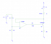
Please help me in this. I am designing a voltage controlled current output circuit. It has an input from 0 to 2.5V and it should give current outputs between 0 - 20mA. I was able to do that with a circuit that looks like:


https://www.flickr.com/photos/41126610@N06/5835196217/in/photostream


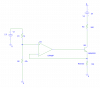
However, I realise what I actually need is something that looks like:


https://www.flickr.com/photos/41126610@N06/5835730028/in/photostream


where the transistor is sinking the output current into R3(Output Load) instead of sourcing from it.


Circuit number 2 however, doesn't work when I tried modeling it with Pspice. It's been giving me such a headache.


Can anybody help me on whether there're any obvious mistakes I've made in the circuit? Also, some explanations why it doesn't work and some suggestions for a better voltage controlled current source circuit would be extremely appreciated.


Thanks. It's my first post on any forums about problems I've had while working with circuits as I really don't like asking questions unless I'm really really desperate for an answer ( like now).


Cheers,

Benjamin
 
First off, you should post your circuits here, not on a third party site - click on 'Go Advanced', and 'Manage Attachments'.

But for your second circuit the input needs referencing to the +ve supply, not 0V.
 
Sorry about the third party site picture. I have attached the same pictures here now.

Thanks Nigel for your reply. May I ask what it means by 'referencing to the +ve supply'? Does it mean my input 2.5V should be +2.5V relative to the +24V supply?

May I also ask why the first circuit works but the second doesnt?
 

Attachments

  • Capture.PNG
    Capture.PNG
    30.6 KB · Views: 269
  • Capture2.PNG
    Capture2.PNG
    28.9 KB · Views: 289
Sorry about the third party site picture. I have attached the same pictures here now.

Thanks Nigel for your reply. May I ask what it means by 'referencing to the +ve supply'? Does it mean my input 2.5V should be +2.5V relative to the +24V supply?

It should be -2.5V relative to the +24V supply.

May I also ask why the first circuit works but the second doesnt?

Because the first one shared a common reference point (0V), the second one didn't (it tried to use 0V and +24V as a 'common' reference).
 
Personally, if this problem was presented to me, the first thing I'd think of is a Howlands Current Source. It's a very neat little setup which allows you to create a constant current output that relies only upon Vin and a resistance value. You can make one constant (the resistance in your case), and vary the other (Vin).

A guy called Ronald W. Parker explains this circuit configuration very well in his book called "Circuits I have known". You can buy the book in print, but it also appears to be freely available online in a pdf version too. Google will be your friend here.

Brian
 
Personally, if this problem was presented to me, the first thing I'd think of is a Howlands Current Source. It's a very neat little setup which allows you to create a constant current output that relies only upon Vin and a resistance value. You can make one constant (the resistance in your case), and vary the other (Vin).

I can't say I've ever even heard of that, but a quick google shows it as very similar to what he's already doing, monitoring the voltage across a sense resistor and using a comparator for adjusting it.
 
It's a little bit similar, but different in that with the Howland Current Source, no input is tied to any reference value. They are both fed back from the output. This can make the circuit seem more complex, but after some explanation the entire thing comes down to iout = vin/r (if all resistances are same value). The book I mentioned, "circuits I have known", does a particularly good job of explaining the circuit operation.

The Howland current source also has an advantage in that it can handle current in both directions, which can be pretty useful in some cases.

Brian
 
May I also ask why the first circuit works but the second doesnt?
As Nigel noted your reference voltage is not correct. Think about it. You need the reference voltage to appear across RSense which is floating at 24V above ground. Thus the reference voltage at the op amp + input needs to be 24V minus Vrsense.

I agree with TR that a Howland circuit should work well for this requirement. A typical op amp should be able to provide the desired 20mA directly.
 
Status
Not open for further replies.

Latest threads

New Articles From Microcontroller Tips

Back
Top