Electro Tech is an online community (with over 170,000 members) who enjoy talking about and building electronic circuits, projects and gadgets. To participate you need to register. Registration is free. Click here to register now.
Welcome to our site! Electro Tech is an online community (with over 170,000 members) who enjoy talking about and building electronic circuits, projects and gadgets. To participate you need to register. Registration is free. Click here to register now.
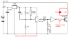
I don't know enough about electronics to change this circuit. The circuit turns the 2N3055 off briefly instead of on. It allows me to vary the pulse which is what I want it to do. So it is backwards. I need help please.
WHat is the load you switch ??
it seems a big transistor (I am not quite sure if the IC can deliver the current to steer it full open if it does I would still put a resistor in the base conection of the transistor
If it is a relay you switch you might want to use a BD 135 type put a 1.8K ohm in the base lead and to use all your other inverter ports put them paralell so they can deliver the current easy and they will not cause problems if as if you leave them with a floating input
Thank you for looking. The load is a coil, and your right the transitor doesn't really allow the full current thru. When I put a relay in for the load, it handles it a lot better. What I'm trying to get the circuit to do, is turn on the transitor when the reed switch is activated, and not off. And as you can tell I know little of what I'm trying to do.
Your circuit will blow up the 74HC14 without a current-limiting resistor. The max allowed output current of an inverter in a 74HC14 is only 25mA. Your circuit makes it try to give 60mA.
The 25mA is amplified by the 2N3055 to a minimum of only 0.6A. If another inverter is paralleled to the inverter that drives the 2N3055 (each with their own 150 ohm resistor) then the base current of the 2N3055 transistor will be 50ma and its load current can be about 1A. The max allowed supply current for a 74HCxxxx is 50mA.
Your circuit will blow up the 2N3055 transistor without a diode to arrest the voltage spike caused when the current to an inductor is turned off.
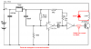
I swapped the parts so that the action is reversed.
Your circuit will blow up the 74HC14 without a current-limiting resistor. The max allowed output current of an inverter in a 74HC14 is only 25mA. Your circuit makes it try to give 60mA.
The 25mA is amplified by the 2N3055 to a minimum of only 0.6A. If another inverter is paralleled to the inverter that drives the 2N3055 (each with their own 150 ohm resistor) then the base current of the 2N3055 transistor will be 50ma and its load current can be about 1A. The max allowed supply current for a 74HCxxxx is 50mA.
Your circuit will blow up the 2N3055 transistor without a diode to arrest the voltage spike caused when the current to an inductor is turned off.
I swapped the parts so that the action is reversed.
The transistor is still normally ON, which is not what he wants. Also, it will not change state until the reed switch opens, which I think is also not what he wants. Move the pot and series resistor to the positive rail, and it should work.
I changed the pot and its resistor over to the positive rail. That made it normally open which is what I want. I have the 2n3055 turning on a relay at the moment, and I noticed that the points don't close until the reed switch opens after it was closed. Also that the faster the reed switch works the pulse stops. I know this becasuse the relay doesn't do any thing. So if I activate the reed switch slowly it sorta works, go a little faster and nothing happens.
I changed the pot and its resistor over to the positive rail. That made it normally open which is what I want. I have the 2n3055 turning on a relay at the moment, and I noticed that the points don't close until the reed switch opens after it was closed. Also that the faster the reed switch works the pulse stops. I know this becasuse the relay doesn't do any thing. So if I activate the reed switch slowly it sorta works, go a little faster and nothing happens.
Did you also move the reed switch to the positive rail, and change the resistors surrounding it also? If you read Audioguru's post, and then mine, you will see that this is necessary to get it to trigger when the reed switch closes.
Just finished switching everything, and nothing happened. I get a small spark at the battery. I even by passed the reed switch, and still nothing. I do appreicate all the help though.
Just finished switching everything, and nothing happened. I get a small spark at the battery. I even by passed the reed switch, and still nothing. I do appreicate all the help though.
This site uses cookies to help personalise content, tailor your experience and to keep you logged in if you register.
By continuing to use this site, you are consenting to our use of cookies.