zachtheterrible said:
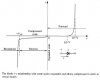
that little picture that i drew @ the begining of the post is PURELY for example. the LED could be a buzzer, or it could be a part of a circuit that requires 2 volts, WHATEVER!! so now that we're not talking solely about an LED, does what has been said by everyone still hold true?
wut i think is being said is that if the right amount of current is achieved, voltage will kind of "fall into place". is this true, or did i miss the whole point :roll:
Ohms law works with voltage, current, and resistance - so you've got to know two of those to calculate the third. In a purely resistive network there's no problem, you can easily work it out (although it may involve some complicated maths in complicated networks!).
However, when non-resistive devices become involved it all goes pear shaped

Your LED example is fairly easy, because you 'know' the voltage drop across the LED you can very simply calculate the voltage across the resistor - which in your example would be 8V. This gives you one of the three, you need one more to calculate the third - in this case you're trying to find the resistor value to give a certain current, so you decide what current you want (10mA, 20mA - 5A!) and then simply calculate the resistance from ohms law.
Obviously the current you decide on could be fairly crucial, depending on the application - the first two of my 'suggestions' would be fine, the third would be slightly inappropriate :lol: The design process involves a lot of decisions about which values to choose - often you only need to choose one, and the rest are calculated from there.
As for replacing the LED with 'something else' it would depend entirely what it was - if it was a resistor, you would know it's value (read the stripes!), and as you want 2V across it you could easily calculate the current through it. This would also give you the current through the other resistor, and you could calculate the value required from that current and 8V (the voltage across it).
A buzzer may well be a more complicated device altogether, and a motor certainly would be - both will have varying 'resistances' depending on their loads and voltages applied.
So there's no 'magic' method, you simply apply ohms law with a full knowledge of the components you're using - otherwise you're likely to do something really stupid :lol:
This is why electronics courses aren't just a few weeks long, and why many years of experience make even more difference!.