Hey gang!
I'll try and describe this as best i can.
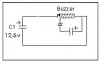
If you take a capacitor (used as a battery) and connect it to a buzzer (like you find in a doorbell - the electromagnetic type).
Then connect a second capacitor & diode across the electromagnet to collect the counter emf or back emf.
Now is there any sort of formula to work out how much power/voltage would be collected in this cap? Ive found some formula which show how to calculate the C-EMF in a coil with an increasing current. But i dont think this applies to calculating the C-EMF created by a collapsing magnetic field of an inductor .... or does it?
examples welcomed
And secondly, by using a diode the voltage/current stored in the cap will leak back into the coil. Is there some simple way to stop this happening?
That way i can compare the actual charge stored, compared to the theoretical figures.
Ive attached an image of the proposed simple setup, is this correct or should the capacitor/diode be connected the other way round?
Thanks alot
Kane
I'll try and describe this as best i can.
If you take a capacitor (used as a battery) and connect it to a buzzer (like you find in a doorbell - the electromagnetic type).
Then connect a second capacitor & diode across the electromagnet to collect the counter emf or back emf.
Now is there any sort of formula to work out how much power/voltage would be collected in this cap? Ive found some formula which show how to calculate the C-EMF in a coil with an increasing current. But i dont think this applies to calculating the C-EMF created by a collapsing magnetic field of an inductor .... or does it?
examples welcomed
And secondly, by using a diode the voltage/current stored in the cap will leak back into the coil. Is there some simple way to stop this happening?
That way i can compare the actual charge stored, compared to the theoretical figures.
Ive attached an image of the proposed simple setup, is this correct or should the capacitor/diode be connected the other way round?
Thanks alot
Kane