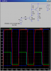
Can someone give me some advice about this simple circuit in the attached schematic? ()
I originally had the circuit with only the T1, but I realized it must be a changed to a high-side switch design. So what I have now is:
T1 = TIP120
R1 = 3k6
La2 Imax ~ 1.5A
La2 Inominal ~100mA
I need help choosing T2, R2, R3 ... or worst case start over from scratch replacing all components. For T2 it sounds like TIP125 or TIP42 are common. (hopefully something that can be found at radio shack. Also I've seen P-FET designs instead of PNP, but not sure if sold locally and/or necessary). If possible I'd like a relatively low power design. The circuit will be used in a system powered by a solar array.
TIP42 I think needs about 560 ohm R3 for to achieve 20mA Ib, correct? I didn't look at the necessary value for a TIP125, but much higher since Hfe is around 1000.
As for R2 I'm guessing anything above 2 or 3k is good?
Also I guess I can increase my R1 since I no longer need the 1A sink it was selected for, but its already at 1mA which is low enough I imagine.
Thanks for any help you can give. Please correct any mistreatments I might have made above. I have done any circuit design in years.
- Casey
P.S I also have a protection diode for the load, but not shown in the schematic.
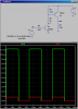
Attachments
Last edited: