Electro Tech is an online community (with over 170,000 members) who enjoy talking about and building electronic circuits, projects and gadgets. To participate you need to register. Registration is free. Click here to register now.
Welcome to our site! Electro Tech is an online community (with over 170,000 members) who enjoy talking about and building electronic circuits, projects and gadgets. To participate you need to register. Registration is free. Click here to register now.
I am requesting for ideas on the above topic. I would like to make a circuit that will regulate the output of a power transformer by raising or lowering the tap changer motor. Thanks
You are going to need to provide much, much more information. How much voltage? How much current? Tap changing motor? Do you mean a transformer with a motor driven variac? Taps on large transformers are generally changed manually based on line voltages to get desired outputs. Variable systems are usually motor driven variacs with reversible DC or AC motors. You raelly aren't providing much information? Also single or poly phase?
You are going to need to provide much, much more information. How much voltage? How much current? Tap changing motor? Do you mean a transformer with a motor driven variac? Taps on large transformers are generally changed manually based on line voltages to get desired outputs. Variable systems are usually motor driven variacs with reversible DC or AC motors. You raelly aren't providing much information? Also single or poly phase?
its a 3 phase power transformer 20MVA with norminal tap 4 having 132kV with 33kV constant output. The bandwidth of input voltages is +-1.31percent for 17 taps. I meant dc motor driven variac. So i will need to raise or lower tap positions by forwarding or reversing motor direction. How are my going to achieve this? Thanks
Man, there are limits that will have to be set. it only has to move to the next tap only when the voltage is outside the range. How are my to set that? Thanks
Is that transformer designed for on load tap changing ?
Large 10, 20, 50 MVA substation TX's with TCOL usually have the electric tapchanger bolted on and switch under load by means of double contacts from which one has a heavy resistor in series to avoid parralleling 2 windings at the same time.
A 110 Volt VT usually drives the voltage regulator. An ac motor with heavy flywheel does the change over, which only does so, when up to speed and the flywheels kinetic energy can do the complete tapchange in one go avoiding the tap getting stuck between two taps.
As your TX has 17 taps which is the normel industry norm.
Yeah, the TX is designed for on load tap changing.
A 110 Volt VT usually drives the voltage regulator. An ac motor with heavy flywheel does the change over, which only does so, when up to speed and the flywheels kinetic energy can do the complete tapchange in one go avoiding the tap getting stuck between two taps.
Atleast have heard of this and its for this that am to design an automatic voltage regulator.
Attached is an example of my transformer records and a sketch of the circuit to make.
Sorry to ask, what do you mean by normel industry norm?
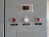
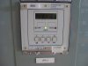
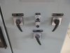
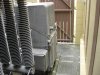
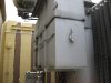
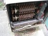
I was in one of the older 33/11 kV subs and took a few photo's of a TCOL
We use a lot of the Alstom KVGC voltage relays.
This is on an ASEA transformer 7.5 MVA
The open box shows the contact drums for the control circuits.
The cubicle on the ground has the drive motor and flywheel in it.
The big box bolted on the TX houses the actual tapchanger.
I have a video on my YouTube channel which showes a TCOL mechanism with flywheel in operation.
I am not that familiar with what you are doing so i can not give too specific advice, but feedback systems (such as servos) use measured signals compared to references to make changes in the system such that the output is regulated between two set points which are usually very close together. For a voltage system, you would divide the output voltage down and rectify it into dc and then compare it to a fixed reference which is set where you want it to be. If the output goes high it would tell the motor to spin one way (to decrease the output) and if the output goes low it would tell the motor to spin the other way (to increase the output). You might build in a little hysteresis to prevent the system from constantly hopping back and forth between two levels.
Guys, its like this project is getting tight for me. Before this, i worked on a personal project with some of you guys and it was a success. Now am looking for design project ideas for my final year at university. I would like to do something concerning power systems and/or equipment. Please advise me on the best possible projects.
This site uses cookies to help personalise content, tailor your experience and to keep you logged in if you register.
By continuing to use this site, you are consenting to our use of cookies.