Continue to Site

Welcome to our site!

Electro Tech is an online community (with over 170,000 members) who enjoy talking about and building electronic circuits, projects and gadgets. To participate you need to register. Registration is free. Click here to register now.

  • Welcome to our site! Electro Tech is an online community (with over 170,000 members) who enjoy talking about and building electronic circuits, projects and gadgets. To participate you need to register. Registration is free. Click here to register now.

Automatic Lights Control

Status
Not open for further replies.

thecritic

Member
Hi friends,
I am trying to make an electronic Device, that will turn on the lights when someone enters the room and turns it off, when exit. The device should actually count the no. of people inside the room, so that, when multiple people enter the room, the light should be switched off, only when the last person exits.

I currently have this plan for the device.

1. Use a up/down counter (CD4011) to count the no. of people inside the room. Whenever the no. isn't 0, turn on the lights and when its 0, turn it off.
2. Use two IR Modules (TSOP1556 and IR Led) to detect whether the person is entering or leaving. and accordingly count up or down.

I can do well with the counter.
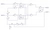
But I need help in this part--> how should I wire those IR Recievers so that, it sends pulse to the up-count Clock pin of CD4011 when someone enters and send pulse to down-count Clock pin when exit.

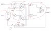
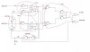
I have shown below my tentative circuit. How should I be modifying it.

**broken link removed**
 
your attachment couldnt be opened, saying invalid, post a right one.
by the way you need a circuit to see the sequence in which the IR sensors are interupted. then it should tell count up/down,
post what you have 1st
 
Hi thecritic,

the CD4011 is no counter. It is a quad 2-input NAND-gate.

Boncuk
 
two sensors & up/down counting when interupted in a sequence

see the attached , may help you, only using 4011 nand gates, it gives you a up/down count enable signal and a count signal/pulse depends on the way the sensors are interupted. the pulse width can be adjusted by the RC time constant.

EDIT: small change is added to the circuit.
 

Attachments

  • count up-down-upgrd.JPG
    count up-down-upgrd.JPG
    43.2 KB · Views: 460
Last edited:
see the attached , may help you, only using 4011 nand gates, it gives you a up/down count enable signal and a count signal/pulse depends on the way the sensors are interupted. the pulse width can be adjusted by the RC time constant.

EDIT: small change is added to the circuit.

I m sorry, I meant to say 40110, up/down counter.
Thanks for your time mbarazeen. But your circuit would be too tedious for me to work around. Couldn't there be simpler circuit that does the same but with fewer components like using flip-flops.
 
it can be completed by four 4011 ICs, any how there are 3 latch flip/flops and two and some and gates.
see the attached instruction, you may get easily how it works, and think of some flip flops to get it done.

let me check for some alternative and reply later
 

Attachments

  • count%20up-down-upgrd.JPG
    count%20up-down-upgrd.JPG
    61.1 KB · Views: 331
it can be completed by four 4011 ICs, any how there are 3 latch flip/flops and two and some and gates.
see the attached instruction, you may get easily how it works, and think of some flip flops to get it done.

let me check for some alternative and reply later

What you are suggesting is exactly what I need. And Thanks for that.
But, see, I would much appriciate it, if it were just few components. Its just cumbersome for me to wire those numerous gates!!!
I don't have any formal knowledge of electronics and the symbols and I just do projects by learning the datasheet of the IC and seeing some example circuits. So, I am quite weak at interpretting your logic circuit.
 
if U5A is for up, then take output of U5B for down, both are complimentry outputs. if one is high other will be low always.

if i explain how it will work,

latch 1 &2 are to hold when the particular sensor is interupted, say at begining if both are at reset state, ie:U1C & U3C are low, (U1D, U3D hight)

if sensor 1 gives a signal U1C changes to H and hold (even the sensor goes to L), same time latch 3 that is for UP/Down signal will latch to say UP (it only hapens when the condition sensor 1 gives a signal 1st)
then sensor 2 gives a signal (person going in) then the same time it will produce a COUNT pulse. and reset when both sensors are unblocked (not interuspted) and after the set delay.

the reverse hapens when sensor 2 is interupted 1st.
 
Last edited:
can easily be done with a PLC and a sensor.
What is that?

And mbarazeen, I need a separate count up and Count down signal, I don't think your circuit does that. And Moreever, By seing your explanation [""...and reset when both sensors are unblocked"" ]
I think that you are supposing that Sesor B should be covered before leaving Sensor A (i.e. the sensors should be placed near enough that a person cant fit in between the two (thereby leaving both sensor unblockde)
But in my actual circuit this may not be the case becasue my sensor produce signal on 'LEAVE' not on 'OBSTRUCT'.
 
YOU CAN GET SEPERATE UP/DOWN, U5A is for UP and get signal from U5B for down.

about sensors, Its not a condition for sensor B to be covered before leaving sensor A. but to give the next count enable, both sensors should be cleared ( or unblocked), then only the system will reset. its to prevent any error counting.

say if one person still passing the sensor B and another person enters to sensor A, this will not count the person entering 2nd. a person should pass through both sensors and leave completely to sense the next person. by mounting both vsensors near by it will do this job.

about your point to make COUNT when person leave take the count out put from U4A on my diagram instead U2A.

Edit: if what you mention is your sensor will give a pulse when person LEAVE, still its ok with the circuit to work properly
 
Last edited:
YOU CAN GET SEPERATE UP/DOWN, U5A is for UP and get signal from U5B for down.

Is this how the circuit works.
1. start U5A =0 , U5B =1
2. Start to Enter (only one sensor obstructed) U5A = 1, U5B = 0
3. Fully enter and stay in . U5A = 0 , U5B =1 (Reset)
4. Start to leave ((only one sensor obstructed), ...... ??
5. Fully leave ...... ??


Edit: if what you mention is your sensor will give a pulse when person LEAVE, still its ok with the circuit to work properly
Yes, I meant that.
 
not exactly,

its like..
1. start (U5A =0 , U5B =1 ) or (U5A =1 , U5B =0) decided bythe last entry In or Out
2. Start to Enter (only one sensor obstructed) U5A = 1, U5B = 0 for IN and U5A = 0, U5B=1 for OUT
3. second sensor is obstructed COUNT=1 , feed back RESET= standby wait until both are cleared. U5A, U5B remain same
4. start to leave ( only 2nd sensor obstructed) = (3)
5. leave completely RESET=1 (circuit reset), COUNT=0, U5A, U5B remains on its last status (no reset)
 
So, suppose noone is inside and the system is at reset state at u5a =0 and u5b =1.
Now, I wire u5a to the count up and I wire u5b to the count down clock input of the counter IC. (the clocks are +ve edge tirggered.)

Now, I try to enter.
1. start to enter u5a =1, u5b=0 . Since u5a changes from 0 to 1, it now triggers count-up. Count ++
2. Both 1st and second sensor is obstructed --> no change in u5a and u5b
3. only second is obstructed --> no change in u5a and u5b
4. leave both ---> no change in u5a and u5b.

Now, Again another person enters then,
1. start to Enter , no change!!! (already u5a=1, u5b = 0)

So, how does this circuit count if second person enters? it don't send any clock signal to count-up this time??

S
 
ok i got your point, i just checked the datasheet, i thought the IC needs three inputs, one is for count/clock, then other two to tell up or down, but in actual you need only two signals.

so you have to use two more AND gates, combine UP& COUNT take out put as UP COUNT
then DOWN& COUNT take out put as DOWN COUNT.

i will post the modified diagram shortly

EDIT: check the circuit for countup and countdown outputs
 

Attachments

  • count%20up-down-upgrd.JPG
    count%20up-down-upgrd.JPG
    64.2 KB · Views: 198
Last edited:
Yeah, Clever, that seems right now. Thanks for that.
I will now start thinking, how could I accomplish this using few flip-flops.
What is the capacitor for, anyway?
 
The capacitor and the resistor is to give a small delay if required, but still it will work without it, since the pulse your sensor sends will be much enough to be recognised and the clock to the counter will have nearly the same pulse width.

just eliminate both the resistor and the capacitor. from my experience an expert will only spend 30min to solder all the circuit with three 4011 and one 5408.

i dont think you can minimize this work by using flip flops. finally you may end up with same number of solderings. just see the pin connections of the ICs its much easier than you think.
 
Last edited:
Status
Not open for further replies.

Latest threads

Back
Top