Menticol
Active Member
Hello!
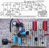
I'm building the famous Audiguru's FM transmitter.
After lots of reading on this and another forums, I got the following "Construction Rules":
1) Spacing between components: < 2 cm
2) Veroboard only - unused tracks must be removed
3) 30" antenna
4) L1 and L2 - see attached file (inductores)
5) Try to make GND track as thick as possible
_____________________________
I had some trouble getting the parts.
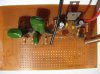
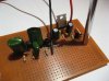
a) I got abnormally huge and ugly polyester capacitors
b) 5-35 pF was not available. I've used 0-70 pF instead
c) The voltage regulator was not available. I've used a lousy LM7805 instead.
d) 160K resistor was not available. Built using two separate resistors in series.
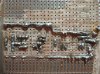
As you already guessed at the beginning of the post, the transmitter is not working. Any suggestion would be very, very appreciated.
PS: The awful ceramic capacitor flying over the board was only a test, trying to find the problem (frustrating). It was placed on a more decent way before taking the picture.
PS2: The microphone was removed, as you can see
I'm building the famous Audiguru's FM transmitter.
After lots of reading on this and another forums, I got the following "Construction Rules":
1) Spacing between components: < 2 cm
2) Veroboard only - unused tracks must be removed
3) 30" antenna
4) L1 and L2 - see attached file (inductores)
5) Try to make GND track as thick as possible
_____________________________
I had some trouble getting the parts.
a) I got abnormally huge and ugly polyester capacitors
b) 5-35 pF was not available. I've used 0-70 pF instead
c) The voltage regulator was not available. I've used a lousy LM7805 instead.
d) 160K resistor was not available. Built using two separate resistors in series.
As you already guessed at the beginning of the post, the transmitter is not working. Any suggestion would be very, very appreciated.
PS: The awful ceramic capacitor flying over the board was only a test, trying to find the problem (frustrating). It was placed on a more decent way before taking the picture.
PS2: The microphone was removed, as you can see
Attachments
Last edited:

 -finally that telescopic antenna looks funny there on the unworking circuit. You can place it once the circuit comes alive!