Continue to Site

Welcome to our site!

Electro Tech is an online community (with over 170,000 members) who enjoy talking about and building electronic circuits, projects and gadgets. To participate you need to register. Registration is free. Click here to register now.

  • Welcome to our site! Electro Tech is an online community (with over 170,000 members) who enjoy talking about and building electronic circuits, projects and gadgets. To participate you need to register. Registration is free. Click here to register now.

Audio splitter

Status
Not open for further replies.
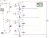
I would like to know if anyone can help me design a circuit that uses op-amps or any other kind of amplifier to take an audio signal from the left speaker and mix it with the right speaker. I have made a small one, but it's hard to calculate what the resistor value needs to be to control gain in the op-amps.

What I would like specifically is to have the audio come in and get mixed so that the signal could be sent out to a VU meter. ex: if there is a lot of music or what not in the left speaker, then the left VU meter would be higher than the right VU meter and vice verse.

The circuit I have posted, is the simple one that I made, I just can't seem to find a consistency between the gain resistors in the op-amp and the Audio level that is put in.
 

Attachments

  • Audio spektrum s&#1.JPG
    Audio spektrum s&#1.JPG
    55 KB · Views: 3,228
I dont understand. If you have two VU meters, why do you need to mix (combine) the L and R signals????

Thread title should say MIXER or COMBINER, not SPLITTER
 
Last edited:
I'm trying to break the signal voltage down. Say that the R input has no signal at all, then the voltage from the left would progressively decrease as it moves towards the right.

I was going to use more than 2 vu meters. I could use up to 10 of them.

I didn't know what the thread should be called, so I just put the first thing that came to my mind.
 
Last edited:
I cant figure out what your circuit is trying to do, but it will not work as you have drawn it unless you connect split power supplies. With the the inputs to all of the opamps referenced to 0V, the opamp supplies need +12 and -12V split supplies.
 
But what if the output needs to be 0V (or close to it)? You may be right, I may need to add a dual rail power supply to the schematic, but I'm not sure how that would affect it.
 
I can't figure it out either.

If it's for audio and not just a VU meter then I'd recommend using an op-amp with a wider bandwidth and faster slew rate such as the TL074.

It's not correctly configured for single supply operation. The side of R5 to R8, currently connected to 0V, should be capacitively coupled to 0V and the non-inverting inputs should be biased at half the supply voltage and capacitively coupled to the input.
 
The circuit will not work anyway since the opamps are not powered. If they have a single supply then the inputs of the opamps might be destroyed when the signal goes more negative than ground.

In my Sound Level Indicator project (it is a VU meter), I use an inverting single-supply opamp (MC3317x) with a single supply and when the input to the input resistor goes negative the opamp's output goes positive then the input to the opamp remains at 0V.

I think it is foolish to use resistors as low as 1k at the inputs to the opamps. 100k resistors will work better.
 
The circuit will not work anyway since the opamps are not powered.

Yes they are, they're just incorrectly powered.

The schematic is confusing, it's a quad package so the + and 0V pins are connected on different op-amps but they're internally connected in the IC. The excess unused power pins should've been deleted from the other components, assuming it's possible in the CAD program he uses.
 
it'a kind of difficult tp piece together what you're trying to accomplish here. are you trying to make some type of VU meter that displays a rendering of the stereo "image"? if so, it's a bit more complex a problem than what you have in that schematic. what you need is a set of differential amps and summing amps, so you get 5 signals out L+R, L-R, R-L, R, and L.. you would then use op amp or resistive mixers to generate the following signals 2L-2R, 2L-R, 2L, 2L+R, 2L+2R, 2R+L, 2R, 2R-L, and 2R-2L. each of these would feed a VU meter, and give somewhat of a picture of the stereo image. it wouldn't be perfect, but it seems to be along the lines of what you're looking for.... if i guessed correctly what you're trying to do.
 
What I am trying to do is make something along the lines of an audio spectrum analyzer without the bandpass filters. (I don't know what it's called)

I have attached a few example pics of what I'm talking about.
 

Attachments

  • Right..JPG
    Right..JPG
    32.7 KB · Views: 272
  • Equal..JPG
    Equal..JPG
    31 KB · Views: 319
  • Left..JPG
    Left..JPG
    32 KB · Views: 270
a spectrum anayzer isn't what you're trying to make then, it's closer to what i was describing, except you wouldn't be using the difference signals beyond the 2L and 2R signals, so you would be using the 2L, 2L+R, 2L+2R, 2R+L and 2L signals. this could actually be done with a resistor ladder, and some op amps that you could trim the gain on to get all of the VU meters reading the same when you have a center channel (L+R) signal (i.e. both channels driven equally and in phase). later tonight i'll draw a schematic along those lines and you can try it.
 
In my Sound Level Indicator project, I have two columns of LEDs indicating the sound level. The input is a mono microphone and the two columns pretend that the input is stereo. It works and looks great.

I used a dual single-supply opamp as a preamp and peak detector and an LM3915 IC for a range of 30db.
I added a simple AGC circuit to extend the range to 50dB.
 
a spectrum anayzer isn't what you're trying to make then, it's closer to what i was describing, except you wouldn't be using the difference signals beyond the 2L and 2R signals, so you would be using the 2L, 2L+R, 2L+2R, 2R+L and 2L signals. this could actually be done with a resistor ladder, and some op amps that you could trim the gain on to get all of the VU meters reading the same when you have a center channel (L+R) signal (i.e. both channels driven equally and in phase). later tonight i'll draw a schematic along those lines and you can try it.

Do you think that that would be the easiest thing to do? I'm all for simplifiying this project as much as possible. What I was origonaly going to do was something similar to what you are describing, except it required each resistor in the resistor ladder to be a different value. The way that you are describing it, all of the resistors could be the same value.

In my Sound Level Indicator project, I have two columns of LEDs indicating the sound level. The input is a mono microphone and the two columns pretend that the input is stereo. It works and looks great.

I used a dual single-supply opamp as a preamp and peak detector and an LM3915 IC for a range of 30db.
I added a simple AGC circuit to extend the range to 50dB.

When all of this is done, the output of each op-amp will feed into the input of another before going to the 3915 VU meter. This was for a friend who was careless in his online shoping and bought 10,000 LEDs (I have no idea how he was able to afford all of those) He only used 10 of them. Now he wants to make an LED cube that he can hook to his suround sound system is his home. I thought that would actually look kind of cool.
 
I was given hundreds of Luxeon SuperFlux LEDs (4 pins, 70mA max) for helping a guy on another forum so I made a very bright red night-light with 36 of them. At 53mA each and with them crowded onto a piece of stripboard and housed in the case from a cassette tape with millions of holes for cooling, boy oh boy does it get hot! The clear plastic case is turning yellow from the heat. They dissipate almost 6W so I need a cooling fan for them.
 
Perhaps they might catch fire?

I wonder if a red light could be used when preparing photosensitive PCBs?

I have a spare three 1W red LED module which could test with some photoresist.
 
I might charge my camera and take a photo of my night-light with it turned off.
 
Status
Not open for further replies.

New Articles From Microcontroller Tips

Back
Top