Continue to Site

Welcome to our site!

Electro Tech is an online community (with over 170,000 members) who enjoy talking about and building electronic circuits, projects and gadgets. To participate you need to register. Registration is free. Click here to register now.

  • Welcome to our site! Electro Tech is an online community (with over 170,000 members) who enjoy talking about and building electronic circuits, projects and gadgets. To participate you need to register. Registration is free. Click here to register now.

audio pre-amp (help)

Status
Not open for further replies.

striker_24

New Member
**broken link removed**

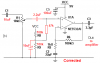
I have questions rgarding our circuit above..Hope members here can help me..

Are the connections above correct? How bout the biasing?

We tested it but the output sound is a bit low..
Then afterwards,what we only hear is noise..
Do u think,what is/are the possible problem(s) of this circuit?

Also,what is the better op-amp to use in this circuit? We are currently using TL074 at NE5532..

What do u think is appropriate op-amp for this one?

Thanks lot!


striker_24
 
Edited the above picture.
 

Attachments

  • f_audiopreampm_d83d35a.gif
    f_audiopreampm_d83d35a.gif
    79.4 KB · Views: 1,069
Last edited:
You forgot to say what is the input device. The gain is much too low for a microphone.
You also forgot to say what is the input impedance of your listening device.

The gain is 1+ (R6/R5)= 7.0 times which is not much gain.

It stopped working maybe because it is built on a breadboard that has intermittent contacts?

sorry for that one..

by d way,the input device is an mp3 player..
 
The output from an MP3 player is about 150mV RMS which is 424mV p-p. The output of your preamp will be 424mV x 7= 2.97V p-p.

What is your preamp driving? it doesn't have enough output current to drive a speaker or headphones.
 
it's an audio preamp with devices mp3 player, cd player, etc. (just like auxiliaries being connected to amplifiers) as the inputs. gain is too little and maybe, due to the bread board as said, stopped amplifying....IC prob maybe a possibility?...
 
It is easy to replace the IC if you think it is bad.
What is your preamp driving?
 
the preamp will drive both head phones and speakers...the head phones are for testing the preamp but the preamp would be connected to power amps that would drive speakers....what''s the sufficient current output to drive these two devices??..thanks..
 
Opamps do not have enough output current to drive low impedance headphones. The max output current is only about 20mA.

Your circuit has a 100 ohm output resistor that forms a voltage divider when headphones are driven so the volume will be low. If you turn up the volume then the opamp will limit the current with severe distortion.
Your circuit has a low value output capacitor that blocks low frequencies below 673Hz when the load is 8 ohms.

8 ohm headphones have a peak current requirement of 160mA at the loudest moments of loud music.

32 ohm headphones have a peak current requirement of 80mA.

The input of most audio amplifiers is 10k ohms. Then the current is only 0.14mA or less.
 
**broken link removed**

by d way,this is the revised schmatic we've made..

It worked but with low gain (volume)..

we are not sure of the connections above (biasing, feedback, input impedance, etc)..

Wat's the possble reason of this? Thanks lot!


striker_24
 
Your new circuit will not work since the non-inverting input of the opamp is at the same DC voltage as the negative supply (ground).
The datasheet for the NE5532 opamp and most other opamps show that a DC input voltage must be within the input common-mode voltage range of 3V more positive than pin 4 and 3V more negative than pin 8.

Your enormous input capacitor is rediculous. A simple calculation shows that its cutoff frequency is 0.03Hz. It should be 3.3uF for a cutoff frequency of 4.9Hz and a flat response down to 25Hz.

The 100 ohms resistor at the output of the opamp forms an attenuator that reduces the output to an 8 ohm headphone 13.5 times. The opamp has a gain of 11 so the output level is lower than the input level.

The opamp will clip and limit the current with severe distortion when the volume is turned up a little.
Low impedance headphones must be driven from a little power amplifier, not an opamp. The NE5532 can drive 600 ohms or more perfectly.
 
Last edited:
the NE5532 ic has one Vcc pin, so + supply is only applied...how can we have DC input voltage within the voltage range? should we have a connection form the +9 supply connected to the input cap? or to another component?
 
Your input DC voltage is at 0V. The opamp can have a negative supply added to pin 4 then the input voltage is within the allowed common-mode voltage range. Your first circuit was like that.

Or the input can be biased with two or three resistors as a voltage divider from the positive supply so that the input DC voltage is at half the supply voltage which is also within the allowed common-mode voltage range. Then the input might need a coupling capacitor.
 
Is this correct?
**broken link removed**

We followed your sticky
opamps-gif.16569
and converted our dual supply into a single supply.

Your input DC voltage is at 0V. The opamp can have a negative supply added to pin 4 then the input voltage is within the allowed common-mode voltage range. Your first circuit was like that.
From the data sheet of NE5532, the op amp has no -Vcc pin. Are you referring to the GND as the 4th pin? https://www.fairchildsemi.com/ds/NE/NE5532.pdf
Can we apply a negative bias on the GND pin of NE5532?
 
From the data sheet of NE5532, the op amp has no -Vcc pin. Are you referring to the GND as the 4th pin?
Pin 4 is the negative supply pin that is connected to ground when there is no negative supply.

Can we apply a negative bias on the GND pin of NE5532?
You can apply a negative power supply to pin 4 or bias the input to half the supply voltage with a resistors voltage divider and connect pin 4 to ground like you did.

You did not add another coupling capacitor between the volume control and the input of the opamp so the volume control shorted the DC voltage to ground. I added a 2.2uF coupling capacitor.

R2 and R3 did nothing in your circuit.

Your resistors R8 and R9 had a value too low. I made them 100k and added a 47k in series so that in series-parallel they equal the resistance of R6 so that the input bias current in each input creates the same voltage loss.
I added a 10uF capacitor as a filter.

The opamp will not drive headphones that are less than 600 ohms. You output coupling capacitor has a low value so it will drive the 10k ohms input of an amplifier.

The gain is 1+ (R6/R5)= 101 which is much too high.

EDIT: I corrected my schematic.
 

Attachments

  • audio preamp.PNG
    audio preamp.PNG
    9.9 KB · Views: 989
Last edited:
Status
Not open for further replies.

Latest threads

New Articles From Microcontroller Tips

Back
Top