hi guys,
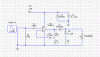
this is a simple audio amplifier i am supposed to built for an assignment in uni.
i also have explain how the circuit works. i have identified C1 and C2 as DC blocking capacitors and C3 and C4 function as a voltage regulator but i still can't exactly figure out what C5 and C6 does. after doing some reading and googling i still can't exactly find the purpose of these two capacitors. all i can say now is that C5 is put there to give a frequency dependent feedback. but what is frequency dependent feedback? what is its purpose in an amplifier circuit? i need your expert help. thx a bunch