I got this idea a while ago to make for my Dad. I was going to design the transmitter and receiver and give them to him on Father's Day. The basic idea was to have a 4 button keyfob transmitter. 2 of the buttons would open various garage door openers and the other 2 would be left empty and could be hooked up to whatever he wanted later. This would require one transmitter and 4 receivers. I had no problem with the receiver, bu the transmitter was a little rough, and never got done.
I didn't get it done because 1) The board I used was too thick for the transmitter case to fit everything in properly and 2) all of my components were very squished together on a single sided board. I figured next time I would go with the 2 sider and a thinner board.
I user the serpac ca-4 case. This case is rather large, but it was the smallest I could find. Does anyone know where I can get a case that is smaller? Preferrably one that runs off of 1 12 volt battery, instead 2 button cells. Either would work I suppose.
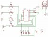
I was using the HT12D/HT12E combination to do this with. Again, no problem with the receiver but the transmitter was a pain because of all the extra circuitry I had to use. Does anyone know of a chip that does basically the same thing, but is only on when it is receiving a signal and then off when it isn't receiving one? The HT12D, if a pin is active it will stay active until it is told to go inactive. This means that on the transmitter I had to add a capacitor to send out the signal slightly longer than when they pressed the button, and 4 diodes that would enable the transmission. I could have just kept that low, but then the battery would run out very fast.
So what I am looking for is a chip that is possibly smaller, possibly SMT, and doesn't have this enable pin stuff and only works when it is being transmitted too.
I hope I have been clear enough that I can get some help. If you don't understand something, let me know.
Thanks!
I have attatched the schematic of the transmitter.
(Note: While my sche says 3V it was actually running on 6)
I didn't get it done because 1) The board I used was too thick for the transmitter case to fit everything in properly and 2) all of my components were very squished together on a single sided board. I figured next time I would go with the 2 sider and a thinner board.
I user the serpac ca-4 case. This case is rather large, but it was the smallest I could find. Does anyone know where I can get a case that is smaller? Preferrably one that runs off of 1 12 volt battery, instead 2 button cells. Either would work I suppose.
I was using the HT12D/HT12E combination to do this with. Again, no problem with the receiver but the transmitter was a pain because of all the extra circuitry I had to use. Does anyone know of a chip that does basically the same thing, but is only on when it is receiving a signal and then off when it isn't receiving one? The HT12D, if a pin is active it will stay active until it is told to go inactive. This means that on the transmitter I had to add a capacitor to send out the signal slightly longer than when they pressed the button, and 4 diodes that would enable the transmission. I could have just kept that low, but then the battery would run out very fast.
So what I am looking for is a chip that is possibly smaller, possibly SMT, and doesn't have this enable pin stuff and only works when it is being transmitted too.
I hope I have been clear enough that I can get some help. If you don't understand something, let me know.
Thanks!
I have attatched the schematic of the transmitter.
(Note: While my sche says 3V it was actually running on 6)