Electro Tech is an online community (with over 170,000 members) who enjoy talking about and building electronic circuits, projects and gadgets. To participate you need to register. Registration is free. Click here to register now.
Welcome to our site! Electro Tech is an online community (with over 170,000 members) who enjoy talking about and building electronic circuits, projects and gadgets. To participate you need to register. Registration is free. Click here to register now.
I'm designing an astable circuit with three transistors that can turn on LEDs for 0.5 seconds, respectively.
i know about circuit with 2 transistors, and in this circuit RL (2.2k) Series with LED.
Please help me
the schematic of circuit with two transistors is attached, The problem is that I do not know the place of third transistor, and Correct values of resistors and capacitors
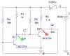
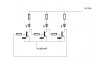
I believe this circuit is what you are after and I suggest you read and understand the text. The circuit is a two transistor astable multi-vibrator circuit with two alternating LEDs. Since you are designing the circuit I also suggest you learn how the timing works in a circuit of this type.
You should not use a supply voltage higher than 6V with this simple circuit.
The reverse-bias emitter-base voltage of the transistors goes to nearly the supply voltage but their maximum allowed voltage is only 6V. With a supply that is higher than 6V then some transistors will have avalanche breakdown of their emitter-base junction that slowly destroys the transistor and messes up the timing of the circuit.
Diodes can be added to fix the circuit.
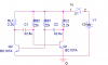
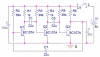
The 2-transistor astable circuit can be extended simply to use any evennumber of transistors. Attached is a 4-transistor astable. The 'on' time of each LED is about 0.6*C*R where, for each stage, C is the capacitor value and R is the value of the resistor connected between +V and the transistor base, i.e. about 0.5 sec for the values shown.
I use LTSpice. Its primarily a simulator but I find the schematic editor pretty useful. Best of all, its a FREE download from Linear Technology. Recommended.
hi again,
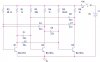
I simulated that circuit with two transistors and it worked completely and I will attach the result, but when i use three transistors , the circuit worked very slowly that i couldn't see the result. how can i solve the problem?
(I used 1.1k resistance to unbalance the circuit, so the circuit can vibrate.
)
simulations are in OrCAD 16.0.
-------------------------------------------------------------------------
I didn't find LED in OrCAD Capture
Each transistor is a common-emitter amplifier that inverts the signal with 180 degrees of phase shift.
Two of them produce a total of 360 degrees which makes positive feedback to make oscillation.
But three of them makes 180 degrees of phase shift for no oscillation.
An even number of transistors will oscillate properly, an odd number will not.
It will have trouble starting because 2 transistors might turn on at the same time.
Look in Google for LED Chaser Circuit. It will have an oscillator (probably a 555 timer) driving a CD4017 decade counter/sequencer. The CD4017 can drive LEDs directly and can have an output connected to its Reset pin for less than 10 outputs. They can be cascaded for many many outputs.
The 2-transistor astable circuit can be extended simply to use any evennumber of transistors. Attached is a 4-transistor astable. The 'on' time of each LED is about 0.6*C*R where, for each stage, C is the capacitor value and R is the value of the resistor connected between +V and the transistor base, i.e. about 0.5 sec for the values shown.
hi again
I simulated the circuit with 2 transistors. the circuit has a few mistakes
the time that's on is 0.7 seconds,while it shoulde be 0.5 seconds
LEDs turn on simulataneously
what should I do?
I modified your circuit so it is like the one Colin posted in post #13 (and I cropped it because your schematic had lots of wasted space).
Try it and let us know if it blinks one on light in sequence or if it blinks one off light in sequence.
the circuit you may be thinking of is a "ring oscillator", which works on an odd number of transistors acting as inverters, causing it to oscillate. I have generally seen it done with MOSFETs, but I have also gotten it to work with BJTs using larger capacitor values.
This site uses cookies to help personalise content, tailor your experience and to keep you logged in if you register.
By continuing to use this site, you are consenting to our use of cookies.

")