//Thank you Alex from https://geektimes.ru/ for help with led array function
//AllAboutCircuits.com
//epilepsynerd.wordpress.com
#include <PID_v1.h>
//This array contains what segments need to be turned on to display numbers 0-9
byte const digits[] = {
B00111111, B00000110, B01011011, B01001111, B01100110, B01101101, B01111101, B00000111, B01111111, B01101111
};
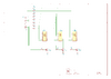
int digit_common_pins[] = {10, 9, 8}; //Common pins for the triple 7-Segment LED display
int max_digits = 3;
int current_digit = max_digits - 1;
unsigned long updaterate = 1200; //Change how fast the display updates. No lower than 500
unsigned long lastupdate;
int temperature = 0;
//Define Variables we'll be connecting to
double Setpoint, Input, Output;
//Define the aggressive and conservative Tuning Parameters
double aggKp = 4, aggKi = 0.2, aggKd = 1;
double consKp = 1, consKi = 0.05, consKd = 0.25;
//Specify the links and initial tuning parameters
PID myPID(&Input, &Output, &Setpoint, consKp, consKi, consKd, DIRECT);
void setup()
{
DDRD = B11111111; // sets Arduino pins 0 to 7 as outputs
for (int y = 0; y < max_digits; y++)
{
pinMode(digit_common_pins[y], OUTPUT);
}
//We do not want to drive the soldering iron at 100% because it may burn, so we set it to about 85% (220/255)
myPID.SetOutputLimits(0, 220);
myPID.SetMode(AUTOMATIC);
lastupdate = millis();
Setpoint = 0;
}
void loop() {
//Read temperature
Input = 0;
for(int i=0;i<50;i++)
Input += analogRead(A0);
Input /= 50;
//Transform the 10bit reading into degrees celsius
Input = map(Input, 0, 550, 25, 400);
//Display temperature
if (millis() - lastupdate > updaterate) {
lastupdate = millis();
temperature = Input;
}
//Read setpoint and transform it into degrees celsius(minimum 150, maximum 350)
double newSetpoint = analogRead(A1);
newSetpoint = map(newSetpoint, 0, 1023, 150, 400);
//Display setpoint
if (abs(newSetpoint - Setpoint) > 3) {
Setpoint = newSetpoint;
temperature = newSetpoint;
lastupdate = millis();
}
double gap = abs(Setpoint - Input); //distance away from setpoint
if (gap < 10)
{ //we're close to setpoint, use conservative tuning parameters
myPID.SetTunings(consKp, consKi, consKd);
}
else
{
//we're far from setpoint, use aggressive tuning parameters
myPID.SetTunings(aggKp, aggKi, aggKd);
}
myPID.Compute();
//Drive the output
analogWrite(11, Output);
//Display the temperature
show(temperature);
}
void show(int value) {
int digits_array[] = {};
boolean empty_most_significant = true;
for (int z = max_digits - 1; z >= 0; z--) //Cycle through each digit
{
digits_array[z] = value / pow(10, z); //We now take each digit from the number
if (digits_array[z] != 0 ) empty_most_significant = false; //Do not display leading zeros
value = value - digits_array[z] * pow(10, z);
if (z == current_digit)
{
if (!empty_most_significant || z == 0) { //Check to see that we do not have leading zeros and display the current digit
PORTD = digits[digits_array[z]]; //Remove ~ for common cathode
}
else
{
PORTD = B11111111;
}
digitalWrite(digit_common_pins[z], HIGH);
} else {
digitalWrite(digit_common_pins[z], LOW);
}
}
current_digit--;
if (current_digit < 0)
{
current_digit = max_digits; //Start over
}
}
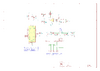
") You can see where the Vin (pin #8) fits in. It's the input to the onboard 5 volt regulator and takes about 7 volts before we have a working regulator. If you want to power the board with a good, clean regulated 5.0 volts you use pin 8 Vin.
You can see where the Vin (pin #8) fits in. It's the input to the onboard 5 volt regulator and takes about 7 volts before we have a working regulator. If you want to power the board with a good, clean regulated 5.0 volts you use pin 8 Vin.