Continue to Site

Welcome to our site!

Electro Tech is an online community (with over 170,000 members) who enjoy talking about and building electronic circuits, projects and gadgets. To participate you need to register. Registration is free. Click here to register now.

  • Welcome to our site! Electro Tech is an online community (with over 170,000 members) who enjoy talking about and building electronic circuits, projects and gadgets. To participate you need to register. Registration is free. Click here to register now.

Aquarium float shut off

Status
Not open for further replies.

London81

New Member
Hi there, first off, your site is epic. I have you guys bookmarked and the ideas you come up with are just epic.

I have decided to dive into building something but just want clarity before I go forward. I want to use a float inside my aquarium to basically switch a pump on and off. Safely obviously is the main perspective. I am in the UK.

I have ordered:

(1) A 240V AC extension cord
(2) Solid state relay
(3) Solid state relay heatsink
(4) 12V DC power supply
(5) Casing
(6) Float valve

Essentially what I a going to do is halfway along the extension cord, I will strip some of the white outer wire off and cut the live wire.

I will strip back the live and attach it to connectors 1 and 2 on load side of the relay.

The 12V DC has two wires and so I will run one wire to connector 3 on the solid state relay and the other I will cut halfway along. I will then attach the float valve to the cut wires before finally attaching to connector 4 on the solid state relay.

Have I got this right? I just want to make sure I am not doing anything dangerous. As no point do I want 240V AC near the fish tank and that is why I am using the relay.

I also want to make sure the positive and negative of the DC adaptor are not the wrong way around. I was going to use a 9V battery instead of the 12V DC adaptor but I wanted something I don't need to keep changing in the future.

Obviously all of this will be in casing well away from the tank with only the float valve being near water. It is actually going to go in my sump attached to the tank so when the water lowers, it cuts off the pump.

Thanks for reading.

Edit: The relay I have is "As-gold SSR Solid State Relay AC - AC 40A 480VAC High Quality" from eBay.

**broken link removed**

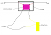
Second Edit, here is a pic I created. Sorry for my lack of Photoshop skills!
 

Attachments

  • PumpControl.png
    PumpControl.png
    201 KB · Views: 184
Last edited:
Hi,

The 12vdc should be isolated from the line, it probably is but might want to check that.

Second, float valves/sensors sometimes stick when they get older. Might want to build in a secondary back up system to check to make sure the pump actually turns off.
 
Thanks for your reply.

The 12V DC adaptor actually can run at 3V all the way up to 12V. When you mean isolated, what do you mean? I am only going to use it to complete the circuit to the relay. Sorry for anything obvious I am missing.

I am actually thinking of wiring 2 or even 3 float valves all wires the same way. It only needs one then to trigger the cut off. Would it be possible to wire in 2 or 3 float valves to the same circuit?
 
Hi,

Yes you can wire more than one in series.

When i say isolated i mean isolated from the line. That means that the 12vdc is derived from a transformer and rectifier with filter caps and possibly a regulator IC. What this means is that if you touch either side of the 12vdc line and touch earth ground, you DO NOT get a shock. If the 12vdc were not isolated and you were to touch either line and earth ground, you would get a big shock. So the 12vdc isolated supply has neither output wire in common with the 240vac line so that there is no risk of shock (to humans or fish).
Most wall warts are isolated but it doesnt hurt to make sure.
 
Hi thanks for your reply.

It is this 12V DC adaptor I've got.

**broken link removed**

The transformer would be inside that. It is basically the same as a phone charger or the power cord for a low wattage toy.

I will have 3 of the floats in a series and that way I have total redundancy. The main issue with aquariums is the pesky snails will sit on the float. Even though the snails are tinier than the O on the keyboard, they are a pain. So I will be housing each inside a transparent container that allows water but no snails to flow through.

This is the type of float I will use.

**broken link removed**
 
I just want to make sure I am not doing anything dangerous.
I'm not sure that's entirely consistent with "Essentially what I am going to do is halfway along the extension cord, I will strip some of the white outer wire off and cut the live wire. I will strip back the live and attach it to connectors 1 and 2 on load side of the relay."
It would be safer to use a proper insulated junction box
 
Hi, thanks for your reply.

Do you have a junction box you recommend? I intend to have the relay and everything else concealed in casing. The neutral an earth wires will not be severed at all. Only the live will be cut and that will be attached to the relay.

Apologies if I am misunderstanding what you mean.
 
Any good electrical retailer should have a suitable box with internal terminals and cable clamps. I had frightening visions of twisted exposed wire ends wrapped in sticky tape :)
 
I am still lost lol. Forgive me here, I am a total dimwit when it comes to electrical stuff.

I won't be using any tape at all. The cut live wire will be attached to the relay. That is the only AC current exposed as the neutral and earth wires will both remain intact. I am not cutting the whole extension cord, just that singular live wire.

That relay will sit inside casing.

The other side of the relay will see the DC current. The three floats will be wired to each other in a series with the two outer floats wired to the DC adaptor. Each one of those will be use a screwed cable connector and no electrical tape in sight :)

Having Googled junction box, I am guessing it is the same thing as the casing I am going to use which is where the relay sits inside. Just the junction box has terminals which I won't be using because the only exposed wires will all be wired to the relay.

Maybe I am missing the point here lol. As I said, I am a dimwit with this stuff. Many thanks for your reply as ever.
 
Hello,


Just one more point about the redundancy. If you are to use three in series that is fine, but you must then also incorporate some means to detect if one of them fails. If one fails (stays on) it must be replaced immediately so that if the others fail sometime later the water does not flow forever. So some periodic checking is necessary to insure that the redundancy is still there and working properly.

Another redundancy here would be to pump the replacement water from a tank that is only filled enough to replace the water in the upper part of the tank. This might not be possible but at least some limit to how much water can flow if there is a problem is a good idea. Watch out for siphoning of the water too even when off, or after the water is pumped for the first time as there could be a little siphon flow which isnt noticed until the tank overflows.
 
I will check them often :) Most likely once every week or so.

I've also wired two smoke alarms up to alert me if the water level increases. Essentially if the water rises to the top of the waterflow, the wires which are located about 3 mm away from each other will have the circuit completed by the water and thus sound the smoke alarm.

The other redundancy is idea is similar to what I've currently got set up. The top few inches of the tank is currently empty. About 10 gallons worth of space. The pump is only in the sump near the top and can only push roughly 10 gallons into the tank.

This device I am trying to build is as much to stop the rather expensive pump burning out as it is to stop the floors getting wet.

The reverse siphon when the pump is switched off would not fill up the sump at all. There would still be in excess of 20 gallons worth of space.

I am still intrigued about the junction box. I figured casing would be enough lol. I am rubbish with this stuff.
 
The junction box and casing are indeed one and the same. It should include a cable clamp to physically anchor the cable to the box; otherwise if the cable accidentally got pulled the live wire could detach from the relay and pose a danger.

Essentially if the water rises to the top of the waterflow, the wires which are located about 3 mm away from each other will have the circuit completed by the water and thus sound the smoke alarm.
Check first that the alarm can be triggered this way. Unless water contains impurities/substances in solution, it can be a surprisingly poor conductor.
 
Thanks for your reply. Yeah the casing has connectors and thanks for clarity there :)

I will be testing the water to see if it does conduct. It is basically tap water with chlorine removed. It does have under 0.1 ppm of ammonia, nitrites and nitrates. If the water method does not work, I will use a float for that solution too :)
 
I've not build it yet. I shall post pics once I have built it. I posted a pic in the first post using the manage attachments thing. Got to love the ease of use of this vBulletin software. A word of advice to the forum admin, don't upgrade to the new vBulletin it sucks big time :)
 
Hello again,

I'd like to see pics too, and also pics of the fish. Fish is my second love :)
 
Status
Not open for further replies.

Latest threads

Back
Top