Continue to Site

Welcome to our site!

Electro Tech is an online community (with over 170,000 members) who enjoy talking about and building electronic circuits, projects and gadgets. To participate you need to register. Registration is free. Click here to register now.

  • Welcome to our site! Electro Tech is an online community (with over 170,000 members) who enjoy talking about and building electronic circuits, projects and gadgets. To participate you need to register. Registration is free. Click here to register now.

anyone know how to use MOSFET's here?

Status
Not open for further replies.
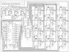
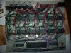
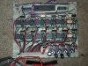
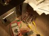
Attached to this message is a circuit schematic of the device as well as the device itself. What it is isa motor control drive board utilizing a PIC for a project that I've been working on for quite a while now. The board works and properly functions for a little bit until at random it seems to just "shut down". Now because of how it would function and then break down gave me three seperate thoughts on how it could be failing, which are :

The LM317's are heating up and eventually shutting down--not the only case as they didn't always heat up when it shut down,

the LM317's arent able to supply all that the 13 seperate motors require--could be and I was referred by a friend to try and increase the capacitance of the capacitors that are attached to the output leads on the LM317's, and

the Motors are drawing too much current from the PIC which causes it to shut itself down. --this is what I"m here for, because when I designed the circuit and chose part values, I was following the datasheet for the required current instead of the motors actual internal resistance/voltage of the circuit (with the datasheet, .7A with the resistance, 2.3A!!) and just lowering the base resistor value of each transistor would go WAY over their rated collector current. I was suggested by my friend that I could relace all of the npn transistors on the board with a MOSFET N type transistor. Only one problem. Other than they are controlled by voltage (from a few online tutorials) I don't know anything else about these things.


so here's my question. Does anyone know of a MOSFET that could fit the parameters required that I could replace the NTE-123A's with (that's what the npn transistors are), how I would calculate the base resistor value (if needed), and do they make MOSFET transistors that are in a case style close to the size of a T092 or a T039? -(if not, then just one that I would be able to swap into the board that doesn't take up very much space--anything at or under the size of a T0220)
any help would be appreciated. Thanks.


--note, as I realize that they do make h-bridges that would replace both the relays and transistors here, I am not at a point where I could do a complete swap like that.
 

Attachments

  • 2009animprojfox.jpg
    2009animprojfox.jpg
    363.5 KB · Views: 266
  • 100_2101.JPG
    100_2101.JPG
    464.9 KB · Views: 234
Most likely solutions:
Make sure you don't have any ground loops between the motor drive and the PIC. It's hard to tell on the breadboard.
I've noticed that you have no capacitors on the 5V line. Add a 0.1uF close to the 7805's output and another close to the PIC.
The LM317s will definitely go into shut down when the motors are started if the motors draw 2.3A at stall. And you probably won't be able to run more than maybe 2 unstalled motors at a time from a single LM317 anyway. And with no heatsinks, the run time limit would be short as well. All would depend on how heavily loaded the motors were.

Less likely:
You could replace the transistors with N type MOSFETs as long as they were logic level MOSFETS and could handle the required current. Something like the IRLZ24 or IRLZ44 would have plenty of current capability. They would drop in with no mods at all as the "base" resistors won't really matter.
 
Last edited:
Not sure it would correct your problem or not, but N channel MOSFETs would be a easy upgrade and a drop in replacement. The gates draw no current except briefly during switching, so they don't normally require a series resistor, however the resistor does no harm and could be left in circuit. You will need to be sure you get what is known as logic level MOSFETS. Normal ones take around +10vdc source to gate voltage to fully turn on. Logic level MOSFETs will turn on fully at 4-5vdc logic levels. Of course you have to select the current rating you need but getting on rated at 10amps or more gives you a good safety margin. This is an easy conversion.

Lefty
 
thankyou guys for the help with this.

So you think that I need to add 2 .01F capacitors within the 5v line?
alright, I'll give it a shot.

I was also told by someone that adding a 100µF capacitor between the output and ground of each LM317 may help.

I'm beginning to think that It is more of a combination of these few problems as when the thing runs, a small # of the motors actually turn while inbetween each one (I have the PIC runing a test cycle running one motor at a time in both forward and then reverse) every so often a motor or two just wouldn't turn on. the few that were the same every time just had a bad connection (which were quickly fixed). however, every so often a motor will still just not turn on at random during almost every test cycle. This is why I assumed it was most likely the PIC, but now it sounds more like it is infact the powersupply.
also, yes the motors will be under a load as they will be used to drive a series of pulleys.


"Make sure you don't have any ground loops between the motor drive and the PIC."

kchriste, when you say this do you mean not to connect the emitter pin from any of the transistors to the same ground that the chip uses?

If so, where else could the PIC's ground connection go?


hopefully in a few days I'll be able to borrow my highschool's oscilloscope to try to find where some of the spikes are being created.
 
So you think that I need to add 2 .01F capacitors within the 5v line?
Yes.

every so often a motor or two just wouldn't turn on. the few that were the same every time just had a bad connection (which were quickly fixed). however, every so often a motor will still just not turn on at random during almost every test cycle.
Put LED with a high value series resistor on each motor IO pin of the PIC. If you use a high efficiency LED and a 2.2KΩ resistor, it won't load the IO pin much but it will still be bright enough to see. Then you can decide if it is a PIC or motor driver problem.

kchriste, when you say this do you mean not to connect the emitter pin from any of the transistors to the same ground that the chip uses?
In this posting is a description of what I mean. Instead of a H-Bridge, you'd have your motor/relay circuit. The MCU is the PIC:
https://www.electro-tech-online.com/threads/isolating-microcontroller-from-motor.87751/#post685708
 
thankyou again.

I don't have any groundloops on the breadboard, and I'll try connecting those LED's to the I/O's of the PIC.


Just one more question. when selecting a logic level MOSFET, are the only two values that I need to look at in the datasheets the voltage and current between the source and drain pins? I'm just trying to find a few other suitable replacements, maybe even a few in slightly smaller case styles than a T0-220 (possibly a T0251 case style)
 
Yes, and make sure that Rds(on) is specified at a Vgs of 4V, or less, to be sure that it really IS a logic level MOSFET and not a misprint. From the Rds(on) spec you can calculate how much power it will dissipate when passing current.
 
Alright, so I've added a 1µF capacitor close to the PIC (adding 2 .1µF one's didn't seem to do much) replaced all of the transistors with IRL530's (all that were avaliable at the store, but they fit the same specifications), and added 100F capacitors to the output lines on all 4 of the regulators. However, it still cuts out like it did before. only differences between before and now are that the motors seem to be rotating woth a little bit more torque, and the relay contacts vibrate a little when they are shut off.


Now, I looked back atthe datasheet for the LM317's that I have and it says that they are able to output in excess of 1.5A. However, the datasheets for other brands of the same part number are only set at a maximum of 1.5A.
could this be why it the board still ceases to work properly?

If so, does anyone know of a voltage regulator that I'd be able to use in this situation that can give out 1.5A?
 

Attachments

  • 100_2124.JPG
    100_2124.JPG
    589.4 KB · Views: 180
right, I almost forgot. I don't have any permanent heat sinks on the regulators, but it still acts the same/cuts off at the same time whether or not I have a few alligator clips on them to help with the heat.
 
With no heatsinks, the LM317s, or any other linear regulator, will only be able to supply 1.5A for a few seconds. Once they heat up, thermal limiting will take effect and their output current will drop dramatically.
Have you verified that the motor that fails to respond is being commanded by the PIC to do so?
 
yes.

What happens is it goes down the line and after running 3 motors it begins to run the 4th one in its first direction, stops,begins to run it in the oposite direction (just like every other motor after the relay switches on) and cuts off about halfway inbetween the time that it is suposed to be running. It does the same thing with the next set if I unplug those first four and let it run until the program gets to the next four.
 
alright, I just tried this now. Even with a small piece of ice (of course within a sealed bag pressed against the 4 regulators while the device is running doesn't change anything.
 
OK, most of your power is going to heat those poor linear-mode pass regulators. You need to quit messing aroung and get them on a serious heatsink. For example, get a piece of 1/8" (minimum) thick aluminum plate about as big as that whole board. (Nice-looking wiring job by the way.) Screw down the LM317's tightly. Thermal compound (heatsink grease) will help. It looks like you could pre-regulate that battery down to about 8 or 9 volts as a possibility for lightening up on power dissipation in the regulators.
To avoid "ground loop", wire the emitters of the drive transistors directly back to the minus pole of the battery with a dedicated power bus. Happily your board is laid out so that you can separate the grounds for the motors and the control circuitry and bring them each back to the power supply (battery) return with separate wires.
Good pictures and fair questions. You are getting two good basic lessons right away here! -Brock
 
Alright, I've got a piece of aluminum with about the same surface area of the board. Would I need to isolate the regulators with mica wafers, or is it okay that the metal tabs sticking up are all connected together on the LM317's?

Also, I've just realized that it is infact the 5th motor that it cuts out on (sorry for the misinformation, it was just really late and motor 4 just doesn't come on at allwhich is why I probably missed it).

This is why I'm still wondering if it really is the heat that is preventingthe device from operating correctly as the regulator that powers motor 5 doesn't get hot at all because there is nothing running through it until it powers motor 5, which then immediately cuts off. (I've already rotated its regulator a few times with some extras that I have and there is no difference.)


once again, thankyou guys for all of your help with this project.
 
What exactly is the source of the 12V? Monitor this voltage, preferably with a scope on DC coupling, to make sure that it stays above 8V at all times when the circuit is running.
 
It is powered by a 12v pack of 8AA's (it sucks that it has to be battery powered)

I don't own a scope, and to borrow my school's mean's I need to put in a request a few days before using it which isn't an option as this is due in 8 days.

I do have a multimeter that I could watch as it runs.

Now because of how soon that I need to complete this and as much as I hate doing this I might end up replacing all of the LM317's with a seperate 3v supply (more batteries) if I can't get it to work in a few days. If I went with this would it be okay to leave everything connected to ground, or do I need to completely seperate the 3v line from the rest of the circuit?
 
Last edited:
You will need to connect the (-) of the 3V supply to the (-) of the 12V/5V supply for the PIC, because of the FETs. No harm will come from this. In fact, using a separate 3V supply will be more efficient.
 
Last edited:
I want to thankall of you for all of your help again. without it, I never would have been able to get this circuit to work.


It was in fact the voltage. When the device was running, the battery pack went all the way down to 6v. After replacing the batteries it worked perfectly. now because when it runs it still gets pretty close to 8v, I was going to do one of thesetwo things just in case it does this when I have to present it.

1-replace the AA's with two 8.4v 1600mAh battery packs and put in a 12v regulator for the relays (I may need help with a # in this case if anyone knows of one) I dunno if this would work for sure, because the packs are 1600mAh and I know at timesthat the motors require 2.3A.

2-have a seperate 3v battery pack with wires ready to be easily swapped out with the giant heatsink/lm317 regulators in case it does cut out. because everything is already connected to the same ground I think it would work

I did end up finding a temporary heatsink to use. (I was originally planning on just using the old PC case in the photo as a giant heatsink once the board was etched.

Now, not all of the motors turn on, but I'm guessing I just have a small short or loose connector on the breadboard somewhere on the line for those motors. If I'm not able to find them I should be in the clear though as in the actual mechanical part of this project the required # of motors was reduced to 8. (I'll end up posting a link once it's completed)
 

Attachments

  • 100_2127.JPG
    100_2127.JPG
    314.4 KB · Views: 182
Last edited:
Since you are using batteries, it makes WAY more sense to have two supplies and eliminate the LM317s. You basically have four options.
1) Change the motors to lower current, equally powerful 12V ones, and eliminate the LM317s.
2) Leave the 12V supply as it is and simply add a separate 3V supply for the motors.
3) Change the 12V supply to a 8.4v 1600mAh battery pack, change the relays to 9V types and add a separate 3V supply for the motors.
4) Change the 12V supply to the 8.4v 1600mAh battery packs, change the relays to 9V types but leave the LM317s in place wasting power as heat. You'll waste a little less power as heat with a 8.4V battery pack as opposed to a 12V one. You'll waste almost no power with a separate 3V battery pack.
 
Last edited:
The only reason that I was trying to connect the motors to the LM317's is because over time, its not always giving out the same voltage as is used to, making the motors spin slower every time and then eventually completely throwing off the mechanical part of this project as the motors don't return to the same place as they used to. (it's what happened in my last project which I think now was a miracle that it was still running at all--on the link YouTube - TSA 2008 ANIMATRONICS)

this project will be controlling something something similar to whats in the video, but far more complicated.
 
Status
Not open for further replies.

Latest threads

Back
Top