Continue to Site

Welcome to our site!

Electro Tech is an online community (with over 170,000 members) who enjoy talking about and building electronic circuits, projects and gadgets. To participate you need to register. Registration is free. Click here to register now.

  • Welcome to our site! Electro Tech is an online community (with over 170,000 members) who enjoy talking about and building electronic circuits, projects and gadgets. To participate you need to register. Registration is free. Click here to register now.

Anyone here used the LM3485?

Status
Not open for further replies.

Blueteeth

Well-Known Member
Hi,

I got about 10 of these very cheaply a while back, along with some P-channel mosfets in the hope to make some *relatively* simple buck converters. I realise there is the MC34063A, as well as national's 'simple switchers', but I have these and want to get them working for me :D

Essentially, I'm after a small footprint replacement for a standard LM7805 linear regulator for medium current applications. The 7805 is the first port of call but when one draws over 150-200mA, with a 12V supply, one quickly requires a heatsink, which takes up space, and I never like anything on my PCB's to get hot :) An LDO would be great but this is mainly for development boards, and I don't want to restrict the power supply to <8V input.

So, LM3845, 5V out. With Vin from say 8-16V which should cover 9,12 and 15V adapters. A current output of 500mA should be possible but it'll probably be running at 100-200mA nominal.

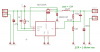
I prototyped the circuit in the datasheet, making sure all my parts were equivilents, with the same value, and similar, if not higher ratings in current/voltage. It is designed to output 3.3V @ 500mA max from 12V. Although the evaluation board applicaiton note (same circuit) claims it will hold regulation for 8-30V input. - According to my setup, this ain't true, so I'm obviously doing something wrong. When using a 10v supply the output drop's at around 100mA, by 200mA, the 3.3v output drops to 2.7.

When changing the feedback resistors for 5v output, it just about manages to hold regulation to 480mA, which is great, but my P-channel mosfet gets HOT. Specs here:

https://www.electro-tech-online.com/custompdfs/2010/08/ND2FNDT456P.pdf

Everything else in the circuit is the same, except the shottky diode is rated for 3A, rather than 1A.

I understand that we're talking, say 80% efficiency here, so with 5v @ 0.5A out, 2.5W , the input being 2.5/0.8 = 3.125, the entire converter must disapate 0.625W (between the switch, diode, IC and inductor). But I'm guessing my efficiency is far lower.

Any example circuits apart from those from national? Seems they removed this device from their 'workbench' software, and no SPICE models are available :(
 
What type of breadboard did you use for the prototype? If the unit is not laid out carefully with short leads and a good ground plane, it may not operate properly.

What value did you select for Radj?

You don't have to guess at efficiency. Just measure the output power (Vo x Io) and divide that by the input power (Vi X Ii).

Post a schematic of your actual circuit.
 
Last edited:
The LM3485 is a part I've used since 2002. I've had great results with it w/ outputs up to 2.7 amp. It is hysteretic, which means variable frequency. Also, the output capacitor must have a well defined esr. If a ceramic or film cap is used on the output, a series discrete resistor must be added.

I've had nothing but great results with the LMN3485. My PFET always stays cool, even at 2.7 amp. I used a TSOP-6 PFET, IRF5800, if I recall. If your PFET is getting hot, here is my advice.

Have you computed all components of switching loss, based on gate charge, Miller effect turn-on & turn-off, & output charge, Qss?

Is the gate drive adequate for the size PFET used?

If you are using too large a PFET, that can be a problem. For 0.500 amp, I cannot imagine you needing anything bigger than a IRF5800, or equivalent. What PFET are you using that is heating up?

Have you computed your switching frequency correctly? If your feedback resistor is bypassed w/ a cap, the fsw is larger than computed.

I am very familiar w/ this part, so if you provide me w/ your selected parts & approach, I can steer you in the right direction.
 
The answer is in your hot PFET. On the reference board, RDSON is used for current sensing. Since you said you used the same circuit, I would assume it's the same. The hot fet means there is a significant voltage drop across the fet, likely activating the current limit. I know what your thinking, my fet has a super low RDS ON. It does, but it also has crap switching characteristics. Total gate charge (Qg) of the refrence PFET is 15nC, your is 47nC. The output capacitance of the ref fet is 90pf, yours is 900pf. What that means is, if your fet and the reference fet are driven with the same output impedance, your fet is going to take at least 3 times longer to turn on and a lot longer to turn off. Your fet spends more time in "limbo" where it isnt quite on or off, its more like a resisitor. The higher the frequency, the more important this is. Judging by the 22uH inductor, I would off-the-cuff guess this circuit was designed to operate around 200-300k. That adds up to alot of switching. That IC is rated at 90% efficiency, so it should only get hot at high currents.
 
Wow, thanks for the reply guys! This is why I love this forum, one can get real world practical advice from those who have more experience. Simulations are all well and good, but they aren't sitting on a PCB hooked up to multimeters :)

Ok, so more info. I have two prototypes, one on single sided FR4, all surface mount. Probably should have ground plane on the other side, but I didn't have any doublesided PCB material at the time. A picture of this is attached.

Second prototype was, believe it or not, on solderless breadboard (I can hear people spitting their coffee at their screen in laughter right now). A mosfet, the LM3485, diode, and inductor were all sodlered to adapters made form stripboard/veroboard, and the connections were made using single core wire as short as possible. I only made this once the above design on the PCB failed to meet my specs, and constantly desoldering/soldering different parts started to get to me.

Some answers to questions:
1) Value for Radj. I used 24k initiailly, but changed this to 47k when the output dropped (assuming it was curent limit kicking in), made no difference. I'm confident the way of calculating it in the datasheet using either the RDSon, or an external current sense resistor is fine.

2) Computed values for switching loses? no :/ I did check the input (gate) capacitance of the MOSFET I was using, noticing is was quite high, significantly higher than the one used in the reference design. Although, it was under 2000pf, so I was hoping it was be 'ok'.

3) Computing frequency was difficult, since I used SMT electrolytic caps from my 'bits box', but thankfully I found the datasheet for them, so I could get a 'rough' estimate of frequency. I also measured it with a frequency meter (which obviously fluttered about) on the MOSFET gate. This reading 300-400kHz.

CafeLogic: I was aware of my MOSFET's gate charge/capacitance, at 1440pf, (instead of ~700pf for the reference design), but it wasn't until you mentioned the output capactiance, as well turn on/off times that I checked the datasheet. You're absolutely spot on!!.... seems it takes an age to turn off. This *also* explains why the LM3845 itself gets rather hot... having to cope with the large gate capacitance of the FET.

I'm afraid I wasn't aware (I should have thought it through) of this specification... as you said, at 300khZ, thats a fair bit of switching, which seems to be beyond what this particular MOSFET is designed for. The only other availabe MOSFET I have is the IRF7205:

https://www.electro-tech-online.com/custompdfs/2010/08/irf7205.pdf

Which has better (ie lower) input and output capacitance, but alas, still has quite a large turn off time.

I originally picked this chip because I wanted to use a small inductor, that is 10-47uH. Some of the 'simple switchers' (as well as the dreaded mc34063A) require up to 220, possibly even 330uH inductors, which, when running for an output of up to 1Amp, can take up a lot of board space. Plus I have quite a few 22uH sheilded 1.5A inductors around, very small and low profile. Also, since the output load can drop as low as 30mA, I wanted my converter to remain relatively efficient at these loads. All in all this chip sounded ideal - no internal switch, but that just means I get to learn more (which I seem to be doing lol).

So, I guess the main problem with my setup is the FET? specifically its turn on and off times, as well as total gate charge. Seems I require a readily available alternative, which can manage a much higher switching frequency.

As an FYI, here's the PCB/schem. Note its single sided, with a couple of jumpers on the other side...far form ideal.

Thankyou all for your replies, as always, any more information/reference designs woudl be much appreciated.
- Blueteeth
 

Attachments

  • LM3485_SCH.png
    LM3485_SCH.png
    29.1 KB · Views: 1,261
  • LM3485_PCB.png
    LM3485_PCB.png
    6.6 KB · Views: 562
Gate charge is probably the key figure you should be looking at. The whole thing is difficult to quantify and the only reliable you can determine switching times in your circuit is with an oscilloscope. So this isn't an exact science but we can guestimate some things.

Code:
Q = Current * Time

Conversely:

Time = Q / Current
Your driver datasheet listed .44 amps for sourcing and .32 for sinking. It wasn't for your Vin but ill use it to estimate.

Code:
On time = 47nC / 0.44 = 107nS
Off time = 47nC / 0.32 = 147nS
Add you typical rise and fall time of 65ns and 70ns and you end up with about 389ns total switching time per cycle, in the real world its probably going to be longer than that. At 330khz, you have 3300ns total per cycle, so you have about 15% or so consumed by switching time. That might not be conducive to the greatest efficiency but I am surprised it doesn't work, I would think it would so there may be something else going on there. The best way to determine that is to look at your rise and fall times by probing the gate with an oscilloscope.

For kicks though, let's contrast this with a modern transistor. For example, the new TI Nexfet CSD25302Q2. Total gate charge 2.6nC

Code:
On time = 2.6nC / 0.44 = 5.9nS
Off time = 2.6nC / 0.32 = 8.2nS

Add tr, 13.2ns and tf, 1.3ns

[B]Total switching time: 28.6ns[/B]
So, as you can see there is quite a dramatic reduction in on/off time possible. Is that going to fix this problem, quite possibly, but I can't be sure. I am guessing you don't have an oscope.
 
Cafe logic, thanks for the numbers :)

Note the prototype on the PCB *does* hold regulation for 5V up to 480mA, its just the MOSFET and controller IC get stupidly hot (did the crude spit test on both). So it seems again you are correct. Whilst the on/off times are low enough for it to actually function, efficiency suffers.

I have read the applications section of the datasheet about 20 times so far, I gather the frequency is dependant of several factors. In terms of component values the two largest contributors are the inductor, and output capacitor, as well as the 'feed forward' cap. Reference designs from national show the output cap to be anywhere from 1uf (for a constant current LED driver, I'm guessing massive output ripple) to 47uF in parallel with a 22uf. The feed forward cap also ranges from 100p to 1nF. The LED driver designs also all use a 6.8uH inductor, and run at ridiculous frequencies - can I assume that the high frequency/low inductor value is purely because the output is used to directly drive and LED? and as such, output ripple isn't an issue for that application?

My output cap is a low ESR 100uF 16V electrolytic. The ESR of which is claimed (by a dodgy datasheet) to be 2.66 ohms. I thought this was high enough as to not require a series resistor for correct hysteric operation. But perhaps the value of 100u is too high for use with a 22uH inductor? I'm afraid I was assuming that the value simply determined output ripple (rather than be a part of the hysteric operation as in this case).

Anyways, I guess the proof of the pudding is in the eating - time to pick up a few decent PFET's with low gate charge and on/off times. Once that is sorted, and keeping my 22uH inductor, I can experiment with output caps. I think I will also use an external resistor for current limiting (got some 0.1R 1% 1206's somewhere) rather than rely on the MOSFET's varying on resistance. Once its functional, and running cool, then comes reducing board space. I and *hoping* to get this on the backside of a single sided development board PCB. Perhaps even with a LDO (with a 0.8v dropout) after the converter to reduce noise. For trouble shooting, I'll add a bypass switch to the buck, so one can use the LDO 'as is', just in case noise form the converter proves to be an issue for my microcontrollers analogue measurements (doubtful).

I realise my posts are long, and possibly boring lol but I shall report back results when parts arrive.

Thanks again cafe, good to have you in the forum!

Blueteeth.

Ps. I *do* have a scope, but its an old analogue one, which weighs more than I do, and is in storage - a last resort for debugging :)
 
OK, well that makes sense, at 5V the mosfet would have a longer duty cycle than at 3.3V. That's the percentage of time it is in the ON state. So perhaps at 3.3, the on state is very short and the mosfet isn't fast enough.

As for your cap, that is probably the rest of the problem. They are basing their charts on a 80 millohm capaciter. 2.66 ohms is atrocious. That ESR is going to cause your converter to run at a much higher frequency. I do strongly recommend you fix the Mosfet issue but you may be able to get it working right now by substituting a low ESR cap.

The converter runs up to 1Mhz, the higher the frequency, the lower the inductance and capacitance required. This is why these DC-DC converters keep getting smaller; advancements in mosfets are allowing higher frequencies. If you ever wondered how you motherboard can deliver 100 Amps to your power hungry Core 2 Quad with those tiny caps, they use what is called a multiphase buck regulator. It's multiple bucks timed in sequence, so that one switches after the other (none switch simultaneously). The waveforms combine at the output before the capacitor. This simulates very high frequencies and allows the use of small capacitors. To address your question, at 1Mhz and 1Amp, you could design the converter for less than 10% ripple with a 1uF cap.

I don't know if the LDO is necessary. Unlike, standard linear regulator they aren't really famous for stability anyway. My recommendation to further reduce ripple is to use a secondary output filter. After the 100uF cap, use a 1uH inductor, leading to a 10uF-22uF low ESR cap, ceramic perhaps. You can't use ceramic on the primary cap though, unless as you stated, you use a series resistor, one of those .1s should be good if you go that route. There is absolutely no reason to think you won't have stable power for your micro. The micro will probably be the noise maker in fact. Sharp turn on times and high frequencies do enable currents to pass all around your board and in between traces, so keep that in mind I guess when setting the frequency and picking the FET. As for the space issue, 500ma is not a lot, If you really wanted to, you could quite easily fit a 500ma switching converter in 1 square inch. Ill post a pic, this is a boost converter for a pressure sensor I designed. It is only good for 100ma, but you get the idea.

**broken link removed**
 
Yep, I'm back to this.

Hey folks, don't know if anyone who replied here are still active members, I hope so!

So, I've gone back to this project, dug out the PCB's, and grabbed the new parts I ordered months ago for it. New PCB, new parts, new design.......no dice. Well 'some' dice...perhaps a die.

The circuit remained much the same as the evaluation board, with the exception of an IRF5800 mosfet (as recommended), an inductor with a higher current rating, and a 150uF NIC neocap I got form a junk laptop motherboard. Datasheet says 50mohm ESR @ 100kHz. My previous '2.66ohm ESR cap was actually speced at 100Hz, not 100kHz, thats probably why its so monsterous.

This time, I grabbed my old scope out and wacked it on the gate of the MOSFET to see the switching frequency and the transitions to see if the MOSFET was fully turning on/off. Well, to my surprise, despite the datasheet claiming one must 'raise' the frequency I found that with a feed forward cap (circuit as specified in the datasheet) of 100pF, output voltage 3.0V, input 10V the frequency is 1.2Mhz. Safe to say the MOSFET got rather hot, as did the controller. The frequency of the controller varied considerably, whenever I moved my hand or the probe, so its very sensitive to noise, and have quite a lot of HF noise on it regardess.

After removing the feed forward cap, it drops to 808Khz. Measured efficiency at my target load of 1.2A out....I get 60-62%. Crap. However, the MOSFET's gate waveform looks lovely and clean, and hardly changed at ALL when I touched the board, or moved the probe, very stable. Also the duty cycle was very close to my calculations (always a plus eh?).

I know this is down to the ridiculous high frequency increasing switching losses, but I haven't found a way to lower it. Everything I try, serves to raise the frequency even higher. Also, the '62%' efficiency, doesn't vary much at all. Even at half load (600mA) I'm getting 61%. The PCB gets hot, but not 'too' hot after running for 5 minutes. So, in a way it DOES work, regulation is spot on, and the output voltage ripple is <20mV. But frankly, its annoying me that I can't lower the operating frequency to something more respectable like 300-400Khz. - unless I use the brute force approach and thats design an external active control loop.

I came across this article:
https://www.electro-tech-online.com/custompdfs/2011/03/803PET22.pdf

Sounded like the perfect solution. Using the same values as they specify, the frequency goes up to... 2.2Mhz. Everything gets hot, regulation suffers. It is 'supposed' to remove the output caps ESR and inductance from the equation that determines the operating frequency... so I was hoping this would eliminate any tolerance effects of my output cap...meaning it's ESR would influence the efficiency, not the frequency. Alas, either they made errors in the values, or, more likely, I'm missing somethign obvious.

I have collected every reference I could on the LM3485, including many service manuals for LCD tv's, and some ACER devices. These all contain schematics, and seem to use the stock circuit, 22uH, using the MOSFET's on resistance as crude current measurement. However.... where they ALL differ is the feedback loop. Some have a feed forward cap of 1000pf, some 330p, some have another cap from FB to gnd, some don't have any. I assume these values were experimented with, given the output caps used to get the best efficiency.

If cafelogic is still around, I would like to discuss this with him, as he was a great help before. Anyone here got experience with hysteretic buck converters? Aside from buying various low esr caps, which are expensive (I have many from old boards, just no 'new' ones) must I be at the mercy of bloody ESR to determine this converters frequency?
 
Did you try using a higher value inductor?

I think I have some lm3485 lying around. I might mock something up and see how it turns out.
 
Cheers man :) I don't want to ask you to spend much time on this, because as many would suggest, I'm seriously thinking about just using a different chip for applications that require stability. Fancy ones with integrated switches, simple control loops etc.. that get the job done.

That said, although it seems that I'm spending far too much time on this one little converter, its (perhaps sadly) much more of a learning exercise rather than one of financial necessity. I never could let things go without knowing everything thats going on. And equations and datasheets don't compare to scoping of an actual circuit. Plus, with the replies from this thread it helped me gain a much better understanding of converters, MOSFET's, power electroics, and even filled in many gaps in my analogue knowledge. All the effort I have spent making up prototype PCB's, desolder/resoldering parts, in my view, was well worth it

But any pointers, I would be very grateful. Its bugging me somethign rotton...
 
Success!

Ok,

After battling with blind 'tinkering' of part values, and effectively making my own spice simulation (using discrete components) in LTspice. I've managed to get the circuit working correctly. Well, at least at a reasonable frequency, and it runs cool at 500mA loads (3v out) slightly warm at 1.2A. I have yet to measure efficiency, since I only have two multimeters, but I'll knock up a precision 'load' so I can get moderately accurate numbers. From rough testing, its 80%+. With Vin = 10v. Vout = 3.0V. (always regulates within 1%, stable at 2.992).

I realise that since this is specific to the LM3485, it probably isn't that interesting to most, but its an hysteretic buck converter which are quite simple and effective converters. I hope it can at least help someone out, whether or not they are using this chip.

Found this link which is an application note for a similar (albeit synchronous) hysteretic converter:
**broken link removed**

The use of 'Radd' and 'Cadd is similar to the previous application note I posted, except Cadd is connected from FB to GND, not Vout. It shouldn't make a differece, but it does! In both simulations and my specific circuit. The addition of these components (along with a coupling cap in seres with Radd) brought the erratic switching frequency down from 1.2-2.2Mhz, to 410Khz. And there it stayed, changing only slightly with load (but there is a lower limit for load).

All waveforms look clean, the inductor current is held in a narrow window, and the output ripple is around 20mV. For my own curiousity, I shall change the output cap to something with a 'crap' ESR. According to my 'rough' simulations, the ESR doesn't seem to impact much on the operating frequency, just the output ripple. This slackens the restriction of using specific output caps to maintain stability and to keep the switching frequency within a range so that all other parts can be chosen within a certain band of values.

So, not my idea! its TI's, but its worked, and seems to make it easier to build a relatively cheap, simple, and very efficient little converter, without head scratching. If anyone (cafelogic?) is interested in the schem, I'll post it with values used and layout.

On side note, as I had to effectively 'build' a circuit that behaves like the LM3485 in LTspice (no native spice model anywhere on the web) I came up with a fairly straightforward pracitcal implementation, using a 555, and LM393 (plus some passives). It's efficiency is still high, and seems to do the job as well as the SMPS chip, but at much lower cost. And certainly something I would consider over a 'simple switcher' when cost is at a premium.

Cheers!

Blueteeth.
 
LM3485 SPICE Model

Hey Cafelogic,

I am also ussing the LM3485. It works as expected when i breadboarded it...but I am also
trying to simulate it using LT Spice.

Could you post how you simulated this?

IT would be much appreciated!

Thanks
 
Status
Not open for further replies.

New Articles From Microcontroller Tips

Back
Top