Continue to Site

Welcome to our site!

Electro Tech is an online community (with over 170,000 members) who enjoy talking about and building electronic circuits, projects and gadgets. To participate you need to register. Registration is free. Click here to register now.

  • Welcome to our site! Electro Tech is an online community (with over 170,000 members) who enjoy talking about and building electronic circuits, projects and gadgets. To participate you need to register. Registration is free. Click here to register now.

Any Simple Push To On/Off Circuit?

Status
Not open for further replies.

Ziddik

Member
Hi, it's been long since i have posted a thread, been kinda busy with life but now back into DIY world and i need help for a flashlight project.

I'm looking for a decent circuit of a push to On/Off circuit. I have designed an awesome flashlight of wood, but I'm having problem with a switch.

I don't like mechanical switches as most of them wear out after a few weeks of use. So any of you experts know any simple reliable circuit, preferably using just transistors or an IC that is commonly available?

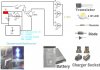
My flashlight battery voltage is 3.7 V and 1 A. My circuit has posted here. Thanks in advance
 

Attachments

  • PicsArt_1443156753547.jpg
    PicsArt_1443156753547.jpg
    257.8 KB · Views: 351
The problem with using an electronic toggle circuit is that it consumes battery power even when the flashlight is off. I'd just look for a better mechanical push-button toggle switch.

Where is the current regulation in your flashlight. Relying on battery internal resistance for current limiting is a problem. Expecting the forward voltage of three randomly-chosen LEDs to match well enough to balance their brightness is also a problem.
 
Last edited:
The problem with using an electronic toggle circuit is that it consumes battery power even when the flashlight is off. I'd just look for a better mechanical push-button toggle switch.

Where is the current regulation in your flashlight. Relying on battery internal resistance for current limiting is a problem. Expecting the forward voltage of three randomly-chosen LEDs to match well enough to balance their brightness is also a problem.

Hi mike, the current in the circuit that I designed is limited with a resistor to the base of transistor , it is also switching the circuit. It is working well and i have designed a nice emergency light with the circuit, it's been running fine for few months, and i want use the same circuit for flashlight project. you are right it will consume power even when not using, but i think there should be some circuit that will draw few mA s when not using?
 
You could make a toggle circuit using a CMOS flip-flop (such as by connecting the /Q output to the D input of the CD4013), that will draw negligible (leakage) current when the flashlight is off.
You would need to de-bounce the switch to avoid multiple toggles of the flip-flop.
 
Hi mike, the current in the circuit that I designed is limited with a resistor to the base of transistor , it is also switching the circuit. It is working well and i have designed a nice emergency light with the circuit, it's been running fine for few months, and i want use the same circuit for flashlight project. you are right it will consume power even when not using, but i think there should be some circuit that will draw few mA s when not using?
The standby current for an electronic toggle will have to be < a few uA, otherwise you will have to be replacing/recharging batteries frequently.

The 100Ω base resistor provides no useful current limiting in the collector to emitter circuit where the LEDs are. The problem with your simplistic LED connection is the brightness of the flashlight is not constant as the batteries are used up. Your light will be bright at first and then dim out before the batteries are used up. A circuit with a proper current-regulator maintains constant brightness even as the batteries discharge.

Another way of saying this it that a proper circuit will have constant brightness for the duration. Your circuit will be bright for the first 10% of the duration, and then dim out during the rest of the duration.
 
Ziddik,
This should work as a Push-ON/Push-OFF switch for your flash light. When OFF, this would only draw current from leakage of the turned-off MOSFETs and the charged capacitor. Both less than a uA. The mechanical push button should last forever.

Mike,
Out of curiosity do you have a constant current circuit that would work for the OP with 3.7v and white LEDs. (I don't like paralleling LEDs.)

Ken
PushOnPushOffMOSFETs 3V.gif
 
hi,
For information if someone designs a current drive circuit.

That 1Watt LED runs at just over 3Vfwd, if you run at 3.3V they fry.
I have 3 of those in series with a 4.7R current limiting resistor running at 600mA from a 12v car battery.
Each LED has the recommended circular heat sink fitted, the LED are running at ~52Cdeg at 22Cdeg ambient.

E

EDIT:
Correction, my LED's of that case style are advertised as 3 Watt rating.
The OP states his are only 1 Watt rated. ??
 
Last edited:
This should work as a Push-ON/Push-OFF switch for your flash light.

I was searching for it while you posted it. I came up with a version of it many years ago, forgot about it, then remembered it when you posted it in another thread last week. Great little puppy.

ak
 
This should work as a Push-ON/Push-OFF switch for your flash light.....................
View attachment 94688
I did a simulation on that circuit and I had to reverse the values of R1 and R3 to get it to work.
Are those two values shown possibly a typo?
 
I must have reinvented the wheel, when I came up with the two MOSFET switch for a PICAXE microcontroller years ago too. Then I saw BIFF383's method if push-0n/push-off.

Ken
 
I did a simulation on that circuit and I had to reverse the values of R1 and R3 to get it to work.
Are those two values shown possibly a typo?

I redrew this in my CAD system and swapped them without realizing it because it seemed like where they should go. Nice catch.

ak
 
Below is my LTspice simulation of the circuit KMoffett posted.
I have to significantly modify some of the resistor values to get a good switching action for all the voltages.
S1 and V1 model the momentary PB switch function.

Note that the circuit requires no de-bouncing circuit and and is insensitive to how long the button is pressed.

The circuit recovery time is only about 50ms after the button is released before it can be pressed to again toggle its state.

The MOSFETs must be logic-level types that fully turn ON (not their Vgs threshold) at 3.3V Vgs (the point where the Ron is measured in the data sheet).

Edit: If it is desired that the circuit always start in the OFF state when power is applied then you can add a 20nF capacitor across R1. That will keep M1 off during the power up time until all the circuit voltages have settled.

Edit 2: You can substitute a CD4049 inverter for M2 if desired. With that you can also eliminate R1 thus requiring only three passive parts for the circuit (besides the PB).
That circuit should also power up in the OFF state, thus not requiring any additional capacitor.

Push ON-Off Sw.PNG
 

Attachments

  • Switch High-Side Bistable 2 MOSFET.asc
    1.7 KB · Views: 172
Last edited:
You could make a toggle circuit using a CMOS flip-flop (such as by connecting the /Q output to the D input of the CD4013), that will draw negligible (leakage) current when the flashlight is off.
You would need to de-bounce the switch to avoid multiple toggles of the flip-flop.
Hi crutschow, do you have any 4013 circuit that can be used in this flashlight? Thank you
 
T
The standby current for an electronic toggle will have to be < a few uA, otherwise you will have to be replacing/recharging batteries frequently.

The 100Ω base resistor provides no useful current limiting in the collector to emitter circuit where the LEDs are. The problem with your simplistic LED connection is the brightness of the flashlight is not constant as the batteries are used up. Your light will be bright at first and then dim out before the batteries are used up. A circuit with a proper current-regulator maintains constant brightness even as the batteries discharge.

Another way of saying this it that a proper circuit will have constant brightness for the duration. Your circuit will be bright for the first 10% of the duration, and then dim out during the rest of the duration.
Thank you for letting me know about a current limiting circuit , do you have any such circuit that will fit this project or to show me an example so i can include them in my upcoming led projects?
 
hi,
For information if someone designs a current drive circuit.

That 1Watt LED runs at just over 3Vfwd, if you run at 3.3V they fry.
I have 3 of those in series with a 4.7R current limiting resistor running at 600mA from a 12v car battery.
Each LED has the recommended circular heat sink fitted, the LED are running at ~52Cdeg at 22Cdeg ambient.

E

EDIT:
Correction, my LED's of that case style are advertised as 3 Watt rating.
The OP states his are only 1 Watt rated. ??
Hi eric, i didn't know the necessity of a current limiting circuit, i have a few questions. The reason i connected leds in parallel is because my voltage is 3.7 v 1 A, o think 3 of those 1 watt leds won't work if connected in series? Is there anything bad if we connect them in parallel in a circuit? Thank you
 
UOTE="crutschow, post: 1235464, member: 85027"]Below is my LTspice simulation of the circuit KMoffett posted.
I have to significantly modify some of the resistor values to get a good switching action for all the voltages.
S1 and V1 model the momentary PB switch function.

Note that the circuit requires no de-bouncing circuit and and is insensitive to how long the button is pressed.

The circuit recovery time is only about 50ms after the button is released before it can be pressed to again toggle its state.

The MOSFETs must be logic-level types that fully turn ON (not their Vgs threshold) at 3.3V Vgs (the point where the Ron is measured in the data sheet).

Edit: If it is desired that the circuit always start in the OFF state when power is applied then you can add a 20nF capacitor across R1. That will keep M1 off during the power up time until all the circuit voltages have settled.

View attachment 94706[/QUOTE]
Ziddik,
This should work as a Push-ON/Push-OFF switch for your flash light. When OFF, this would only draw current from leakage of the turned-off MOSFETs and the charged capacitor. Both less than a uA. The mechanical push button should last forever.

Mike,
Out of curiosity do you have a constant current circuit that would work for the OP with 3.7v and white LEDs. (I don't like paralleling LEDs.)

Ken
View attachment 94688
thank you km, i will give it a try if i can find the mosfet here. I'm currently looking for a circuit with Cd4013 or 4027 as i have a few of those ics in collection
 
3 of those 1 watt leds won't work if connected in series? Is there anything bad if we connect them in parallel in a circuit?
hi Z,

The problem is that the 3 LED's forward parallel voltages may not be matched, ie: say one is 3V and an other is 3.3V.
The 3V LED could pass much more current than the 3.3V LED, so its possible the 3V LED could fry.

A worst case would be say LED's at 3V , 3.2V and 3.3V, the 3V would fail then the 3.2V fail ..

If you can match 3 LED's from a larger batch quantity, that would be a good solution, if not, a low value resistor in series with each LED.

E
 
T

Thank you for letting me know about a current limiting circuit , do you have any such circuit that will fit this project or to show me an example so i can include them in my upcoming led projects?

To make a high power flashlight that tries to drive three 1A 3.3V LEDs starting with 4V battery, I would wire them series and drive them with a step-up current regulator **broken link removed**
 
...but I'm having problem with a switch. I don't like mechanical switches as most of them wear out after a few weeks of use...

If you have 3 1A LEDs in parallel, you are asking that poor push-button to switch 3A. No wonder it burns up...
 
Your voltage is not always 3.7V!
A Lithium battery is 4.20V when fully charged that will quickly destroy your LEDs without limiting the current.
The battery is 3.2V when its load should be removed but then the LEDs might not light or might be very dim.
Then the average voltage during a discharge is 3.7V.

I have a cheapo Chinese flashlight with 24 ordinary (but matched) white LEDs in parallel and powered from three 1.5V cheap "super heavy duty" AAA cells in series without anything to limit the current except the internal resistance of the battery.
The power switch is intermittent because it is a cheap piece of junk. Of course the cheap battery did not last long so when I replaced it with Name Brand alkaline cells I added a current-limiting resistor.

I should replace the switch with a better one. On second thought, I should replace the flashlight with a better one.:banghead:
 
Status
Not open for further replies.

New Articles From Microcontroller Tips

Back
Top