Continue to Site

Welcome to our site!

Electro Tech is an online community (with over 170,000 members) who enjoy talking about and building electronic circuits, projects and gadgets. To participate you need to register. Registration is free. Click here to register now.

  • Welcome to our site! Electro Tech is an online community (with over 170,000 members) who enjoy talking about and building electronic circuits, projects and gadgets. To participate you need to register. Registration is free. Click here to register now.

Any Ideas As to why circuit keeps breaking

Status
Not open for further replies.
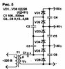
I recently built the ballast circuit from this website. https://www.repairfaq.org/sam/jshidbal.htm However a few odd issues arise such as it says that it will draw around 6 amps at 12 volts, however mine only pulls about 3 to 3.3 amps with most arc bulbs, except metal halide those will pull around 4.5 amps for some reason. Secondly, whenever I connect the voltage multiplier for the halide bulbs it will strike them up once and then it will try to strike the next time it turns on but after 7 or so attempts it destroys the transistors. Also I have a very big heatsink on my 2n3055's but they still get very very hot. Can someone tell me why it might be destroying the transistors. I've wired it up correctly and it oscillates. (By the way this is a spare project before someone mentions LED'S)
 
What transformer are you using? The original article notes that it is an air-gapped one which limits the current.
(See the first paragraph below the schematic).

You should be able to add a reasonable value resistor, eg. 1K or 10K, between the transformer and the input cap of the voltage multiplier, with little effect other than reducing surges.
 
T1 transformatör primer gücü fuko ve histeriz kayıplarını düşünmez isek sekonder gücüne eşittir. T1 transformatöer çıkış akımı R3 direnci girişin de 6 kat daha düşüktür.T1 transformatöer çıkış gerilimi ise R3 direnci girişin de 6 kat daha büyüktür. Çünkü giriş gücü= Çıkış gücüdür. Pin=Pout. Bu devre ile sadece içinde gaz bulunan lambalarda etkilidir. Örneğin floresan lambalarda daha çok etkilidir. Flamanlı lambalar da istenilen verim alınamaz. Flamanlı lamba bağlanırsa giriş 12V akımı artar T1 transformatör sekonder sargısı kısa devreye gider.Devrenin diğer bir adı gerilim katlayıcıdır. Devre de ki R3 direnci ark atlamalarına karşın kısa devre olmasın diye konulmuştur.
 

Attachments

  • Gerilim Katlayıcı.jpg
    Gerilim Katlayıcı.jpg
    24.3 KB · Views: 161
T1 transformatör primer gücü fuko ve histeriz kayıplarını düşünmez isek sekonder gücüne eşittir. T1 transformatöer çıkış akımı R3 direnci girişin de 6 kat daha düşüktür.T1 transformatöer çıkış gerilimi ise R3 direnci girişin de 6 kat daha büyüktür. Çünkü giriş gücü= Çıkış gücüdür. Pin=Pout. Bu devre ile sadece içinde gaz bulunan lambalarda etkilidir. Örneğin floresan lambalarda daha çok etkilidir. Flamanlı lambalar da istenilen verim alınamaz. Flamanlı lamba bağlanırsa giriş 12V akımı artar T1 transformatör sekonder sargısı kısa devreye gider.Devrenin diğer bir adı gerilim katlayıcıdır. Devre de ki R3 direnci ark atlamalarına karşın kısa devre olmasın diye konulmuştur.
To paraphrase:

"The design is only suitable for gas discharge lamps".
The OP appears to indicate that is all he is using, anyway?
 
What transformer are you using? The original article notes that it is an air-gapped one which limits the current.
(See the first paragraph below the schematic).

You should be able to add a reasonable value resistor, eg. 1K or 10K, between the transformer and the input cap of the voltage multiplier, with little effect other than reducing surges.
I using a homemade transformer with a 3.5 mm airgap. I'll try adding a resistor when I get another transistor. Could the voltage multiplier be somehow pulsing the secondary too much and inducing a big voltage/current spike in the drive or feedback windings and killing the transistor. I've also noticed that the transistor that fails goes short circuit across everything.
 
Going through the transformer details, it may just be damaging the transistors.
Each half of the primary is apparently 15 turns, which will have near 12V applied.

The secondary is 20 turns end to end, so a higher voltage than the primary; One end is limited to the base conduction voltage of the transistors, so the other end is driven strongly negative, likely putting more than -12V on the other base.

The datasheet Vbe rating of a 3055 is only -7V.

I'd be tempted to add eg. 2.2 Ohms in series with each base, plus another 2.2 Ohms in series with a high speed rec between base and emitter so that conducts when the base goes negative.
That should protect from both excess base current and excess negative voltage.

You could even try it with one ohm resistors, that should still be within safe limits.
One of the primaries is 15 ct 15, and the other is 10 ct 10. The secondary is 700 or soo turns.
 
I suspect the issue is the quality of the design, it's really crude and nasty - and absolutely critical on the exact design and construction of the transformer. There are endless threads on these forums from people who can't get similar circuits to work, mostly crude mains inverters.
 
I suspect the issue is the quality of the design, it's really crude and nasty - and absolutely critical on the exact design and construction of the transformer. There are endless threads on these forums from people who can't get similar circuits to work, mostly crude mains inverters.
I'm not sure if its the design because it will run just fine without the multiplier and it will get small flourescent lamps and mv lamps going. However it only blows the transistors when I connect the multiplier stack.
 
I don't think it really increases the load because all it does is boost the voltage to the ignition point of the lamp. Then it becomes basically passive.
 
Status
Not open for further replies.

Latest threads

Back
Top