tomizett
Active Member
Not a very exciting mystery object, but can anyone help my identify this component?
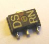
I *believe* that it is an NPN transistor - it measures correctly for an NPN with a meter (ie, two diodes pins 1>2 and 1>3), although I've not been able to put one on a component analyser yet. I believe the package is a SOT89.
It is from a voltage-controlled-amplifier, which features a large number of these components (at least some of) which are connected as trans-diodes (that is, pins 1 and 2 shorted).
One of the devices has failed, and I would like to replace it - in reality, I suspect I'll need to replace all of them to ensue a good match.
This one (the borken one) is marked "DS RN", although some others from other modules are makred "DS RM", so I suspect the "RN" may be a batch or date code.
I've looked everywhere I can think of... any help really apreciated!