Continue to Site

Welcome to our site!

Electro Tech is an online community (with over 170,000 members) who enjoy talking about and building electronic circuits, projects and gadgets. To participate you need to register. Registration is free. Click here to register now.

  • Welcome to our site! Electro Tech is an online community (with over 170,000 members) who enjoy talking about and building electronic circuits, projects and gadgets. To participate you need to register. Registration is free. Click here to register now.

antenna circuits

Status
Not open for further replies.

3six

New Member
I got to thinking about antennas the other day and realized that I don't really know how they operate from a circuit theory perspective. I've learned the basic theory about electromagnetic waves and how they are created by passing a current through a wire, that passing an ac current produces waves of the desired form/frequency, that kind of thing.

My question is this: In all of the circuit diagrams I see that contain an antenna, the antenna appears to just be left hanging off of the circuit; it's not connected to ground or the rest of the circuit. Like in this simple FM transmitter circuit:
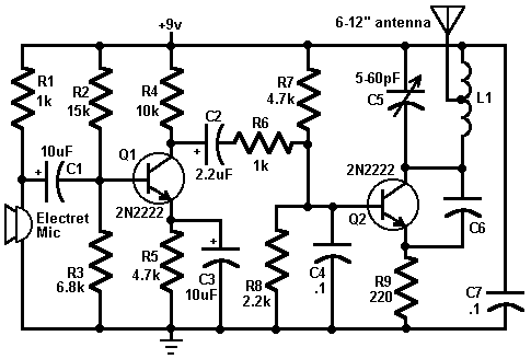
fm_transmitter.gif


When I look at actual devices that transmit signal via an antenna, there is usually just a single coaxial cable going to the antenna. So, how do they transmit? In order for the antenna to radiate the waves, it has to have current go through it, and if there is no path to ground(or whatever) through the antenna, how does any current get in there?
 
Last edited:
I got to thinking about antennas the other day and realized that I don't really know how they operate from a circuit theory perspective. I've learned the basic theory about electromagnetic waves and how they are created by passing a current through a wire, that passing an ac current produces waves of the desired form/frequency, that kind of thing.

My question is this: In all of the circuit diagrams I see that contain an antenna, the antenna appears to just be left hanging off of the circuit; it's not connected to ground or the rest of the circuit. Like in this simple FM transmitter circuit:
fm_transmitter.gif


When I look at actual devices that transmit signal via an antenna, there is usually just a single coaxial cable going to the antenna. So, how do they transmit? In order for the antenna to radiate the waves, it has to have current go through it, and if there is no path to ground(or whatever) through the antenna, how does any current get in there?

In short I would say the circuit you show is a very simple transmitter , not obeying effective designing. The simple wire acting as an antenna looks very lossy , though it will work . As this antenna is connected to the Tanks circuit it starts radiating energy as its conducting time varying current and any conductor if gets a time varying current will radiate anergy . The question of GND doesnt comes here . Actually think it in terms of dissipating coulombs field when the charge on the antenna tends to its maximum.

-Adi

Thats not quite accurate. The wire antenna if 1/4λ works like any other antenna. It reflects back to signal ground even if it is the size of a pencil eraser. For above type of circuit, it is wise to use a large groundplane.

The ground acts like the other 1/4λ.
 
Last edited:
The simplest antenna to examine is the Dipole ... All other antennas are just variations of the Dipole Antenna.

The Dipole Antenna has a specific physical length, for a given frequency of transmission and reception. At the design length, a correctly cut dipole antenna will be resonant at the specified frequency. In a simplistic sense, this means that only an electromagnetic wave of the designated frequency will interact with the antenna...Other frequencies are rejected.
In actual practice, it is usually possible to tune the transmitted and received frequencies within a given range, by using reactive L and C elements within the radio set.

A concept that is similar to resonance is impedance. The general design goal is to have the output impedance of the transmitter and receiver circuit be equal to the characteristic impedance of transmission line, and also of the antenna itself. If the impedance magnitudes of the various elements are not the same, or similar, then electromagnetic waves are reflected from the antenna or transmission line .... These are sometimes referred to as standing waves. Standing Waves are counter-productive, since the intended electromagnetic power and energy are not going to the antenna, but are reflected back. If the impedance quantities are reasonably the same, then the electromagnetic power will be transmitted through the transmission line and radiated from the antenna.

One interesting fact about an antenna is that the current flowing through it has a magnetic field component, and also a separate electric field component. The magnetic field part is generally oriented to be along the length of the antenna, and is large or significant only over the short field, or over a very local area ...The magnetic field attenuates, or reduces as a function of 1/R², where R is a measure of distance from the antenna. However, the electric field radiates at right angles to the length dimension of the antenna, and is only attenuated, or reduced as a function of 1/R. ... Electronic communication, as we know it, is only possible because of the far ranging E field. If the E field were reduced in the same fashion as the magnetic field, according to 1/R², radio, TV, cellphones, and whatever else would only reach a city block or so.
 
Take a quick look at the ARRL website. Under TIS pages (technical information) you'll find a number of articles that might help.
 
Such a simple circuit isn't very good because it takes its output from the tank circuit which means a small change in load can alter the frequency. You need a buffer between the antenna and RF oscillator to act as a buffer.
 
Thats not quite accurate. The wire antenna if 1/4λ works like any other antenna. It reflects back to signal ground even if it is the size of a pencil eraser. For above type of circuit, it is wise to use a large groundplane.

The ground acts like the other 1/4λ.

You can say that its a fundamental fact with antennas, but my take was that he was worried regarding galvanic contacts . I have been using Nordic/Ti chips which does makes contact with the GND.
-Adi
 
Last edited:
man, i've tried to reply like 4 times and I seem to keep getting modded or something. anyway, i'm thinking about these circuits based on what i've learned in my DC circuits course. To me, antennas seem to just be hanging wires and from what i've learned, current won't flow into a dead end like that.

To me it looks like this:

**broken link removed**

the hanging wire in the diagram would be the antenna, but no current should be entering that wire, unless it gets connected to something, right?
 
Last edited:
man, i've tried to reply like 4 times and I seem to keep getting modded or something.
Possibly because you have a low post count, the post does not appear until it has been "passed" by a moderator. Not to worry, it is here now.


anyway, i'm thinking about these circuits based on what i've learned in my DC circuits course. To me, antennas seem to just be hanging wires and from what i've learned, current won't flow into a dead end like that.

To me it looks like this:

**broken link removed**

the hanging wire in the diagram would be the antenna, but no current should be entering that wire, unless it gets connected to something, right?
The simple transmitter circuit which you showed earlier may appear to look like your sketch, however:

1 Current does flow in a transmitting antenna (and a receiving antenna, but a much lower level).

2 There must be two parts to the antenna, or current will not flow.

3 For a basic dipole antenna, the current flows through free space from one leg of the antenna to the other.

4 If you disconnect one leg of the antenna, it will still work but with greatly reduced efficiency, if you measure the antenna current with an RF ammeter, you will see that the current has dropped considerably.

5 A monopole antenna, just a single wire as in the transmitter circuit shown earlier has to have a "second leg" for the returned antenna current, the second leg is the 0volt line (ground line) of the transmitter itself. This is a very inefficient setup, which can be improved considerably by connection a wire to the 0volt line (ground line) of the transmitter.

6 For correct operation of a dipole antenna, each leg should be a quarter wavelength long at the operating frequency.
In the case of the monopole antenna, that should also be a quarter wavelength long, as should the wire connected to the transmitter 0volt line, sometimes referred to as a "counterpoise earth".

OK?

JimB
 
Your question is a very good one and shows that you've been paying attention in class. I used to wonder exactly the same thing, how is it that current can flow when there does not appear to be a circuit? To understand the answer, you need to understand AC current and how it behaves as the AC frequency goes very high. So first some basics.

When you push current into a wire, any wire, it takes time to get to the other end. When you study DC, they don't mention this to simplify things for the beginner. Even if you study AC motors and such they don't mention it at first. But it is a key factor to understand. The current doesn't travel to the end of the wire in zero time, it actually travels at nearly the speed of light. I agree that is very fast, so fast that you can pretend it is instantly at the other end in DC circuits. But, imagine if the voltage with which you are pushing the current into the wire is alternating. Let's also imagine that there is a resistor at the other end of the wire, and the other end of the resistor is connected to earth ground. In this way, we don't have to worry about where the current goes for now, as it goes through the resistor to ground.

Next, let's say that the input voltage is alternating with a frequency of 100 MHz (or million cycles per second). Now, imagine that that voltage at some point in time happens to be at a peak. For simplicity's sake, we will also pretend that the input to the wire is resistive (it's not, but we have to start somewhere, so let's pretend it is). So when the voltage hits its peak value, the current that is being pushed into the wire at that instant is also at a peak. Now, this little packet of charge that we call the current, the charge that was started down the wire at the voltage peak, starts to move down the wire at the speed of light (its a bit slower than that, but we are simplifying). Meanwhile, the voltage back at the input end of the wire starts to go down (its AC remember, and I'm assuming the shape of the AC is a sine wave). When that voltage reaches 0, our little packet of charge has travelled 0.75 metres down the wire. That isn't really very far is it?

Notice what has happened here. We have a voltage at the end of the wire that has gone down to zero, and yet there is a current flowing 0.75 metres down the wire. Isn't that weird? This is the at the heart of your question. As the voltage goes up and down at the "input" to our wire, the current that travels away from the input is varying. So if it were possible to take a snapshot of the current along the wire at any one time, it would have an AC shape, going up and down along the wire. So, as this shows, you have different amounts of current along the wire when you have AC.

Your antenna does not have a resistor at the end going to ground. In an antenna such as this, with the end floating in space, the current at that end must be zero. This is obvious because it is impossible for the current to go anywhere off the end of the wire, so this "locks" the current value at that point to zero. But because it is AC current, it doesn't have to be zero anywhere else on the wire. Your transmitter circuit is putting an AC voltage at the "input" end of the antenna wire so you are pushing current into the wire at a frequency of around 100MHz. So the current along the wire, if you take a snapshot of it to freeze it at any one time, will have a pattern of highs and lows, and there will be a zero amount at the end of the wire.

In fact it is a bit more complicated than that. In a wire like this, what happens is that the current flows to the end of the wire and has nowhere to go, so it bounces or reflects off that open end, reverses course and starts to travel back to the input end. When you add the instantaneous currents at any point, including the sum of the current going one way with the current going the other way, we see the sum of the two have a static pattern that happens to be the same shape as the initial input voltage (the most common shape of AC is the sine wave shape). We call this static pattern a "standing wave" because it just stands there and doesn't move. The standing wave patten is exactly zero at the open end of the wire. It is this standing wave pattern of current that causes the radiation.


Anyway, the key is that the current is indeed zero at the end of the wire, but because it is high frequency AC, the current everywhere else is not zero. And as the current flows up and down the wire the net total current at each point along the wire forms a pattern that doesn't move, called the standing wave. The shape of this standing wave determines how the antenna radiates.

Hope that helps.
 
Hey Ron, Thats an awesome post! I have always found antennas a bit mysterious too. I enjoyed reading that.:D
 
that helps a lot, thanks ron.

JimB said that an antenna requires two parts so, would my sketch not work as a monopole antenna?

also, when jim said that current flows through free space in dipole antennas: did he mean this like this:**broken link removed**

i guess one side of the antenna is connected to coaxial the shielding as ground right?
 
Last edited:
man, i've tried to reply like 4 times and I seem to keep getting modded or something. anyway, i'm thinking about these circuits based on what i've learned in my DC circuits course. To me, antennas seem to just be hanging wires and from what i've learned, current won't flow into a dead end like that.

To me it looks like this:

**broken link removed**

the hanging wire in the diagram would be the antenna, but no current should be entering that wire, unless it gets connected to something, right?

It might help before trying to understand all the complex details about antennas to just consider them a simple transducer.

They convert electromagnetic waves into AC current and AC current into electromagnetic waves. This is similar to how speakers and microphones work, transducing air pressure waves into AC currents and AC currents into air pressure waves.

A transducer is any device that converts one form of energy to another form of energy, however not all work in both directions. Electrical currents and radio waves are two totally different things. Any electrical conductor has the capability of acting like a antenna, however for best efficiencies the antenna should be designed and sized for the specific frequency to be used.

That help?

Lefty
 
Well. 3six, yes your sketch shows a monopole antenna. As you can guess, the monopole means "one pole" and of course dipole means two poles. Like a magnet, two poles in an antenna is the simplest complete form, where the current at one end is symmettric to the current in the other end. A monopole actually works much like a dipole (or at least tries to), but many people are not aware of this. In order for a monopole to work well, it needs a "counterpoise". This, one of my favorite words, simply means that there has to be something to carry the current that balances with the current on your monopole. In the ideal monopole, the counterpoise is what most people call the ground plane. In an antenna such as your monopole, the counterpoise is whereever the balance current can go. This is usually the transmitter board and any metal nearby. You can imagine that the transmitter board is quiet small, and there may not be much metal nearby, so in this case your monopole is really a poor one as it finds very little counterpoise.

I was not entirely happy with Jim's statement that the current finds a path from one leg of the dipole to the other. Jim knows his stuff, so he was simplifying, but this statement can be misunderstood. The trouble is that a more accurate statement is going to be a bit more complicated. But let's give it a try.

The current cannot literally flow through space as we understand current. The energy that goes hand in hand with the current is in the form of a magnetic field. The energy that goes hand in hand with the voltage that pushes the current is in the form of an electric field. As the current flows on the antenna wire as I described, it is accompanied by a magnetic field and an electric field that surrounds the antenna. The fields link one leg of the antenna to the other. Now, hang on to your seat, because its going to get a bit more complicated again.

These fields that link the two legs of the dipole don't just sit there. They are actually flung away from the dipole. Or, a better description might be that they are pushed away, one after the other, as they are formed (they are AC fields). In this way, the fields detach from the antenna and fly away from the antenna. So, the energy that flows into the antenna, the energy that is in the form of current, voltage, magnetic and electric fields, is actually lost into space. The antenna radiates energy.

So, when we put a voltage into the antenna, we cause a current to flow into the antenna. Have you learned ohm's law yet? You know how we calculate that current is voltage divided by resistance? You might wonder what is the resistance in this case? Well, in a resistor the current and voltage together define an amount of power, and the resistor's resistance turns this power into heat. We have a similar idea in antennas. The power that goes into the antenna is not turned into heat however, it is turned into electromagnetic power which leaves the antenna and radiates away. So, we define something called the "radiation resistance" to represent how much current flows in an antenna when a certain amount of voltage is applied. As before, the current equals the voltage divided by the radiation resistance. Its kind of neat that it works the same as any circuit in this way.

So, the antenna actually works like a part of a circuit in that it has a resistance, and when put some AC voltage across it, a current flows that is equal to the voltage divided by the radiation resistance and the power that is generated flows away as electromagnetic power.

When I say that we put voltage across the terminals of an antenna it makes sense when you picture a dipole. But it doesn't seem to make sense when you picture your monopole. Well, in fact the dipole in your case has one side as the wire "antenna" and the other side as your transmitter's circuit board copper (and any wires leading up to the board other than the antenna). These are the two terminals that form your "circuit" if you like.
 
Last edited:
Well, in fact the dipole in your case has one side as the wire "antenna" and the other side as your transmitter's circuit board copper (and any wires leading up to the board other than the antenna). These are the two terminals that form your "circuit" if you like.
you meant monopole, right? so, antennas all have two terminals, but with monopole antennas, the counterpoise is one of them, is that correct? the dipole has two easily identifiable terminals, but the circuit still seems to have hanging wires. what I took away from your previous post is that it's possible for high frequency AC current to flow into a hanging wire(antenna), but it bounces back at the end and creates a standing wave, which gets radiated as electromagnetic waves.
 
you meant monopole, right? so, antennas all have two terminals, but with monopole antennas, the counterpoise is one of them, is that correct? the dipole has two easily identifiable terminals, but the circuit still seems to have hanging wires. what I took away from your previous post is that it's possible for high frequency AC current to flow into a hanging wire(antenna), but it bounces back at the end and creates a standing wave, which gets radiated as electromagnetic waves.

Well, no I did mean dipole, but if its confusing don't worry about. My meaning is that the dipole and monopole are not so different after all. You seem to get that correctly. I think your understanding is pretty good.
 
RadioRon, please edit your last post again to change your Ohm's law statement. You say I=ER, which would be very interesting :)

Oops. Thanks for the correction. Guess I was in too big a hurry on that one. Edited as requested.
 
Status
Not open for further replies.

Latest threads

New Articles From Microcontroller Tips

Back
Top