frosty12345
New Member
hi guys, 1st post so please be gentle ") ive had a quick search but cant find a definate answer.
ive had a quick search but cant find a definate answer.
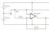
im trying to build a 741 opamp with a gain of 1k.
its wired up as per the diagram with both offset pins grounded, and supplies of +-15v
if i supply the device with +-10mV square wave, im expecting +-10V.
i get a steady -14V which suggests the device is at its supply limit, but it does not oscillate between +-14v.
the device also gets really really hot (hot enough that i burnt myself on it earlier).
does anyone have any suggestions?
thanks
alex
ive had a quick search but cant find a definate answer.im trying to build a 741 opamp with a gain of 1k.
its wired up as per the diagram with both offset pins grounded, and supplies of +-15v
if i supply the device with +-10mV square wave, im expecting +-10V.
i get a steady -14V which suggests the device is at its supply limit, but it does not oscillate between +-14v.
the device also gets really really hot (hot enough that i burnt myself on it earlier).
does anyone have any suggestions?
thanks
alex