Continue to Site

Welcome to our site!

Electro Tech is an online community (with over 170,000 members) who enjoy talking about and building electronic circuits, projects and gadgets. To participate you need to register. Registration is free. Click here to register now.

  • Welcome to our site! Electro Tech is an online community (with over 170,000 members) who enjoy talking about and building electronic circuits, projects and gadgets. To participate you need to register. Registration is free. Click here to register now.

Anemometer

Status
Not open for further replies.

jay543_uk

New Member
Hi all
I am building a anemoter for my nephew and need alittle help with the electronics. I have seen a few different ideas on the net but desided to make one using bits i no i had around already.For the rotary pickup i am using a brushless DC PM Motor from a old hard drive. My problem is i want to connect it to a pic 16f876a and measure the pulses that it gives off as the wind rotates it.

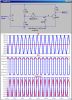
I put the motor on a scope and rotated it and it generates a sine wave form which increases in frequancy and voltage the faster you turn it, from my basic understanding on micro pics i need to turn the sine into a square wave and keep its voltage between 0v-5v.

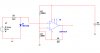
Can i use a schmitt trigger to do this.

i found a few ideas on the net and draw up diagram, can any one tell me if im close to solving the problem or should i just give up now.

thanks for any help any one can give me.

regards jason
 

Attachments

  • wind.jpg
    wind.jpg
    90.6 KB · Views: 951
What's the voltage from the motor? If it's high enough, you can just connect it PIC pin with a series resistor. If its amplitude is >0.7V, then you can use a transistor to drive the pic. If it's too low, then an amplifier might be needed.

And yes, a schmitt trigger will work, you just have to set suitable thresholds.
 
What is the d.c. resistance between the motor wires ( motor shaft not moving)?
 
thanks for the reply, i span the motor with it connected to a multimeter and the voltage varied from 0v to 35v. it seems to shoot up high the faster it turns, thats why i was going to use a schmitt triger. I was hoping to triggger it at a 0.3v threshold, that would meen that the trigger would put out 5v from 0.3v and turn back to 0v when it drops below the 0.3v threshold.

does that sound ok
 
hi, i think it was about 5 ohms but im not shore till i test it tomorrow, what difference can that make ??

My design relies on having DC continuity. Look at the attached. If works for all voltages from the tachometer from 0.1Vpp to 100Vpp. Tricky, huh?
 

Attachments

  • Draft50.png
    Draft50.png
    36.6 KB · Views: 734
Hi jay543,

you might want to take a look at this transistorized and digitized linear anemometer circuit.

It is small and has no moving parts.

If you are interested in the PCB layout just PM me. I have designed it using Eagle.

Regards

Boncuk
 

Attachments

  • AIRFLOW.PDF
    157.3 KB · Views: 1,037
  • Anemometer.gif
    Anemometer.gif
    35.6 KB · Views: 946
Last edited:
hi boncuk thanks for the reply, my nethew us 5 and wants one that spins round on top of this shed, im gona read into your design as iv got some ideas which your design may work for.

im gonna try out mikemi design but i havnt got any 2n3904 trans around but do have a few c547b trans, they both seem to be npn type so can i just use the c547b instead
 
worked fine but the trans switched when the motor put out about 350mv, is this because im using a bc547b instead of the other trans or can i change some resistors to change the switching voltage
 
The high-impedance resistive voltage divider which feeds the base through the motor should bias the transistor just on the verge of turning on. With no rotation, what is the PIcPort voltage level. It high, make R2 slightly bigger. If Low, make R1 slightly bigger.
 
i got your circuit to work MikeMI by changing the resistor values slightly but can you explain how the circuit works, i have a very basic understanding of transistors and dont really no how the circuit works, sorry if this is a simple one but iv not had much to do with transistors

thanks

jason
 
The transistor is used as a common-emitter amplifier. As such it has a voltage gain of about 30. When the generator puts outs a small voltage (~0.1V), the gain of the amplifier amplifies it to almost 3V at the output. As the output of the generator gets higher, the amplifier still amplifies it, but the output now saturates, turning the wave into a square-wave. Since all the PIC wants to see is the period of the wave (not its shape), that is fine.

Since the generator puts out such a wide range of output amplitudes, 0.2 to 100V, some form of current limiting is required. That is why I used resistors with high resistance values to create the voltage divider. The primary purpose is to set the transistor's base bias operating point. The secondary purpose is to limit the current that flows as the generator puts out large voltages.

The base-emitter path into the transistor behaves like a forward-biased diode junction for generator current flowing into the transistor. The reverse diode across the base-emitter transistor junction is there to conduct when generator current flows in the other direction. It effectively protects the base-emitter transistor junction from excessive reverse voltage, and makes it so that the generator sees a symmetric load for both positive and negative voltages...
 
Last edited:
how does changing r2 make my out go from 5v to 0v, does that change the current flowing into the base of the tran or does it change the voltage? This may be a simple thing to you guys but im lost, iv been trying to look it up on the net but im just lost in all the maths to work it out
HELP!!!!

also with the motor connected to this circuit i only get about 1.5v from it, is this because there is a load on the motor now???
 
Last edited:
i now have a square wave input into my pin but im not shore the best way to measure it, I need to convert the pulses to wind speed so i guess i need to measure the pulses over a given time so i no the speed of the motor.
What is the best way to do this??
i am proply going to use a 18f pic
i get 6 pulses to one revolution of the motor
i believe i will only have to measure up to about 150hz

thanks for every ones help
jason
 
Status
Not open for further replies.

Latest threads

Back
Top