Electro Tech is an online community (with over 170,000 members) who enjoy talking about and building electronic circuits, projects and gadgets. To participate you need to register. Registration is free. Click here to register now.
Welcome to our site! Electro Tech is an online community (with over 170,000 members) who enjoy talking about and building electronic circuits, projects and gadgets. To participate you need to register. Registration is free. Click here to register now.
What is the 330K at the output supposed to do? Oh, that is a LED?
A high brightness LED will illuminate brightly enough to be seen even in sunlight with 5mA flowing through it; 10 is better.
With 9V out of the battery, and two VceSat drops (~0.3V ea), less the Forward voltage drop across the LED (~1.8 to 3.3V, depending on color), the LED current limiting resistor will have ~5.5V across it, mean that to get 5mA, it would have to be 5.5/0.005 = 1K.
What is the 10K from emitter to ground supposed to do?
Yes the output is the LED and the purpose of the emitter to ground is the high low voltage flow which allows the connection of the LED to turn on and off with taking a wire and changing between negative and positive I believe?... I'm not the greatest with this but all I know its suppose to turn the LED on and off would you be able to assemble this on a breadboard ?
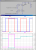
Here is a simulation of your (modified) circuit. I had to move the LED and current limiting resistor to the high-side of the circuit. With the LED in the emitter side, there was some leakage current through the LED even when it is supposed to be OFF. Note that current flows through the LED I(D1) only when both V(A) and V(B) are high at the same time.
This site uses cookies to help personalise content, tailor your experience and to keep you logged in if you register.
By continuing to use this site, you are consenting to our use of cookies.