Dragon Tamer
Member
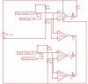
This may seem like a really stupid thing to ask, but I just can't seem to figure out how to get this to work. What I'm trying to do is take a comparator for a circuit that I later intend to make into an IC for myself and for sale. I have several problems that I can't seem to workout.
The way I want the IC to work is that there are 3 voltage supplies, one for the chip, one for the first input and another for the second input. That's the analog part. The voltage supplies for input 1 and 2 are for an internal reference for the comparator. There is an input pin that will either be connected to Vcc or ground to establish whether the inputs are a sinking or sourcing input (one for each). I can't seem to get the source/sink control pins internal circuit to work properly. I'm trying to use simple logic gates to power transistors for the comparator (because the actual input is still analog). I want the output of the comparator to be high when the input is respective to the source/sink control pin. IE: s/s High, input high, comparator output high, and s/s low, input low comparator output high.
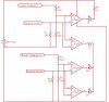
My second problem is that I want the IC to drive both common anode and common cathode LED's. This is the part that has given me the most trouble. I want the output of the comparator to drive transistors or logic gates, something. There is a Common Anode Common cathode pin that will switch the outputs to their opposite state respectively.
Any help with this is greatly appreciated. I don't care what the inputs are, all I want is for simple logic gates only to be used.
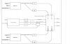
PS: there are 3 outputs and 2 inputs
The way I want the IC to work is that there are 3 voltage supplies, one for the chip, one for the first input and another for the second input. That's the analog part. The voltage supplies for input 1 and 2 are for an internal reference for the comparator. There is an input pin that will either be connected to Vcc or ground to establish whether the inputs are a sinking or sourcing input (one for each). I can't seem to get the source/sink control pins internal circuit to work properly. I'm trying to use simple logic gates to power transistors for the comparator (because the actual input is still analog). I want the output of the comparator to be high when the input is respective to the source/sink control pin. IE: s/s High, input high, comparator output high, and s/s low, input low comparator output high.
My second problem is that I want the IC to drive both common anode and common cathode LED's. This is the part that has given me the most trouble. I want the output of the comparator to drive transistors or logic gates, something. There is a Common Anode Common cathode pin that will switch the outputs to their opposite state respectively.
Any help with this is greatly appreciated. I don't care what the inputs are, all I want is for simple logic gates only to be used.
PS: there are 3 outputs and 2 inputs