vlady_2009
New Member
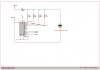
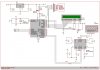
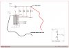
attached schematic (PICcircuit.jpg) shows PIC attached to RS232/PC etc which controls HEF4051B 8-channel analogue multiplexer/demultiplexer that switches between various voltage divider ranges (analogInput.jpg). The voltage divider ranges are approximately 4, 3, 2 and 1.5 (at this stage just for testing purpose - I also checked operation of the PIC code/RS232/HEF4051 by selectively turning on LED's from PC keyboard input in a previous circuit). I'm using a handheld DMM to measure the output voltage of the voltage divider as the analogue switch selects different ranges. Results below are fine when I use the PIC Vdd supply as the input to the voltage divider, and also no problem when using a battery.
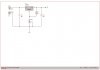
But when I use input voltage from a LM1086 (LM1086VarVoltage.jpg), which with a 20V input from a "wall wart" allows variable voltage up to ~17V, voltage from the output of the voltage divider isn't correct (the PIC Vdd is from a 7805 from a seperate wall wart). I plan on using the output from the voltage divider (with a Zener for over voltage protection after R1 of the voltage divider, and some more code in the PIC for auto ranging selection) into the ADC of the PIC, with display on the LCD/RS232.
I'm doing something wrong with the GND's? or is the approach using the HEF4051B wrong? ("Funny" values for R1 and R2 are because these are actual measurement of the resistors used in the circuit).
R1 9930 9930 9930 9930
R2 3300 4600 9800 17710
Vout/Vin 4.0 3.2 2.0 1.6
Vin 4.9 with Vin from uP supply
Vout Calc 1.22 1.55 2.43 3.14
Vout Meas 1.24 1.58 2.45 3.15
Vin 6.27 with Vin from battery
Vout Calc 1.56 1.98 3.11 4.02
Vout Meas 1.60 2.04 3.12 4.00
Vin 6.01 with Vin from LM1086IT adj voltage reg
Vout Calc 1.50 1.90 2.99 3.85
Vout Meas 1.21 1.46 2.11 2.63
Thanks in advance for any help/advice.