Continue to Site

Welcome to our site!

Electro Tech is an online community (with over 170,000 members) who enjoy talking about and building electronic circuits, projects and gadgets. To participate you need to register. Registration is free. Click here to register now.

  • Welcome to our site! Electro Tech is an online community (with over 170,000 members) who enjoy talking about and building electronic circuits, projects and gadgets. To participate you need to register. Registration is free. Click here to register now.

Amped Tone Burst Generator

Status
Not open for further replies.

dogman_k

New Member
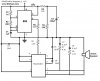
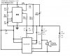
I found this diagram while I was searching for a circuit that I could use to simulate electric fencing: Tone Burst Generator Circuit - www.ECELab.com.

The circuit performs as I want it to with one exception...it is not loud enough. I found some 1W speakers and while they were louder than the 0.1W speakers I was able to get from Radio Shack, they are still not loud enough.

I would like to increase the volume and what came to me was to put in a small amp. I don't know where to put it though. I am driving this from a single 9V battery, and if possible would like to stay with that. The speakers are from a set of ASI Audio Tech EMCPU1-0G rated at 1W with input sensitivity of 300mW. Could not find impedance.

Thank in advance for the help.
 
Figured it out

Doing some more research on this, I realized that the circuit already included what I think is a single transistor common emitter amp. So to crank up the volume, I just needed to adjust the resistor going into the base and/or the resistor going into the collector. I managed to get a significantly louder tone by dropping the 10k resistor going into the base down to a 100 ohm resistor.
 
It is a hopeless low power circuit that wastes a lot of battery power.
If you use a TDA2822M power amplifier IC then the power will be so high that you must reduce the supply voltage to 6V from four AAA or AA alkaline cells. The TDA2822M amplifier has a voltage gain of 100 so the signal from the 555 must be attenuated with two resistors.
 
Suppose I were to put in a TDA2822M. Looking at the data sheet, I'm guessing that I would first take the 2N2222 out of the circuit and use something like Figure 16, but only one side of it since am only using one speaker. What size resistors would I need off of the 555?

And while it would be very nice to have the circuit use less battery, the duty cycle on this will be about one hour powered on, and probably no more than 5 minutes of that actually generating a tone per week.
 
The datasheet for the TDA2822M shows a low power stereo amplifier with 2 speakers and huge output capacitors in figure 1 and figure 16, and also shows the bridged higher power amplifier with 1 speaker and no output capacitor in figure 2.

To reduce the 4.5V p-p from the output of the 555 to 80mV at the input of the amplifier you use a 100k resistor in series with 1.5k. The input of the amplifier is connected across the 1.5k resistor.

Why do you use an awful-sounding square-wave tone?
 
To answer your question, I am using it because this was the first circuit I found that fit my needs that I could actually build on my own. My needs being a loud noise that would sound for 1-2 seconds when a button was pressed.

And this is my try at a modified version of the circuit based on Fig. 2. I don't have capacitor polarities marked because I could not figure them out.
 

Attachments

  • circuit-tone-burst-modified.jpg
    circuit-tone-burst-modified.jpg
    57.5 KB · Views: 250
The 1W from the amplifier will not be much louder than a cheap clock radio.

You made a few mistakes on your schematic:
 

Attachments

  • 555 with TDA2822M amp.PNG
    555 with TDA2822M amp.PNG
    52.4 KB · Views: 511
It does not need to be ear shattering, just loud enough to hear clearly from about 6-8 feet over the clash of epees.

And here is my revised schematic:
 

Attachments

  • circuit-tone-burst-modified-2.jpg
    circuit-tone-burst-modified-2.jpg
    57.9 KB · Views: 294
Your revised schematic is correct.
The frequency of the oscillator will be 320Hz so the coupling capacitor should be about 33nF.
 
Status
Not open for further replies.

Latest threads

New Articles From Microcontroller Tips

Back
Top