Electro Tech is an online community (with over 170,000 members) who enjoy talking about and building electronic circuits, projects and gadgets. To participate you need to register. Registration is free. Click here to register now.
Welcome to our site! Electro Tech is an online community (with over 170,000 members) who enjoy talking about and building electronic circuits, projects and gadgets. To participate you need to register. Registration is free. Click here to register now.
No it doesn't, although it's a VERY good idea to include it. You should also use a special transformer designed for battery charging, these are designed to current limit - a normal transformer may well destroy itself on a flat battery. There's also no need for the capacitor in a crude battery charger!.
so a 120v \ 12v 5amp transformer wont work? I made the charger and had a volt meter hooked up to the battery leads but when I plugged it in the diodes blew.I would buy a charger but where Im at (not in usa) they want 100+ dollars for a manual 6a charger.
Is there something I can add to protect the trans.?
One of the reasons the diodes failed is because they are only rated for 1 amp.
If you have a 12Vrms 5amp transformer, you should have at least 5amp diodes, I would goto 10amp, if possible.
Connect a 5amp slow blow fuse in the output from the charger to the battery. [say, in +V lead]
The charger should also be mains powered from a fused supply, 3A fuse should be OK.
I would also ground the -V supply from the charger to the mains ground, just in case the charger transformer develops a fault.
As chargers are sometimes used outdoors, it would be advisable to use a RCCB in the mains supply line.
the current limiting resistor goes in the hot main wire? if so Im calculating with 120v and 5amps? how many ohms resistor ? 5X24=120 but its not a 24ohm res and is it the kind thats in like a ceramic rectangle?
5 Amps at 120 Volts is 0.5 Amps at the primary side of the TX.
A 12 Volts lead acid (car batt) requires between 13.7 and 14.4 Volts to fully charge.
At your TX secondary you should aim for an output voltage within that range.
A good value to start with is 10hm: which will give you a 5 volt drop at the primary and about 0.5 V at the secondary.
Rating should be 2.5 Watts. Get a 7 Watt ceramic wirewound resistor or put smaller ones in parralell. 3 of 30 hm: 2 Watts each (makes 10hm: )
You can do a bit of trial and error here. Be carefull with mains wiring and put on well insulated standoffs.
A batt charger is self regulating anyway. Initial high charging current when batt is flat, voltage of batt increases, hence less charging current, till a status is reached that charger volts equals charged batt volts.
the current limiting resistor goes in the hot main wire? if so Im calculating with 120v and 5amps? how many ohms resistor ? 5X24=120 but its not a 24ohm res and is it the kind thats in like a ceramic rectangle?
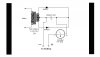
I would fit a resistor in the secondary side, NOT the mains side - either in one of the leads from the transformer to the bridge, or in the positive lead to the battery.
Before I actually got round to buying a battery charger (which cost very little anyway), I used to 'throw something together' whenever I needed to charge a battery. A simple and easy current limiter is a bulb, try a headlight or foglight bulb in the positive lead and see what current you get - if the battery is dead flat the bulb will even light to tell you!. I used to use an old front foglight, which was a damaged one I saved - this always worked fine.
This site uses cookies to help personalise content, tailor your experience and to keep you logged in if you register.
By continuing to use this site, you are consenting to our use of cookies.

 hm: which will give you a 5 volt drop at the primary and about 0.5 V at the secondary.