Continue to Site

Welcome to our site!

Electro Tech is an online community (with over 170,000 members) who enjoy talking about and building electronic circuits, projects and gadgets. To participate you need to register. Registration is free. Click here to register now.

  • Welcome to our site! Electro Tech is an online community (with over 170,000 members) who enjoy talking about and building electronic circuits, projects and gadgets. To participate you need to register. Registration is free. Click here to register now.

amp grounds

Status
Not open for further replies.

aleks990

New Member
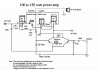
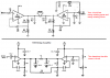
when i see an amp schematic i see a lot of grounds, does all that grounds need to be connected to the ground of the amp-chip or all together ? if not where do all those grounds go ... and where do i connect the volume potentiometer on the pcb? i would appreciate if u help me ;) heres a circuit with the grounds and without the potentiometer so that u could explain me what to do,where to put the potentiometer,thanks.
 

Attachments

  • a100.jpg
    a100.jpg
    68.6 KB · Views: 170
  • 16wattamp.gif
    16wattamp.gif
    9.9 KB · Views: 151
You copied an amplifier circuit that uses obsolete LM383 power amplifier ICs that is completely wrong. You should copy the circuit in the manufacturer's datasheet like I did. In the datasheet is a recommended printed circuit board design that shows what connects to what.

All grounds must be connected together including the ground that is between two opposite-polarity power supplies on your first circuit.
The volume control connects to the signal source, ground and the input coupling capacitor of the amplifier.
 

Attachments

  • LM383 bridged amplifier.PNG
    LM383 bridged amplifier.PNG
    34.5 KB · Views: 276
All the ground symbols need to be connected together, but it is almost an art when considering current flow in a way that high current sections must not be allowed to interfere with delicate stages like pre-amps. This is where the term, "star ground" was invented. The final ground point will have several circuits approching from different stages so physically, it looks a bit like a star.
 
thank u guys very much, so the grounds all connected together go to the ground of the power supply, but i cant still figure out where the volume control goes can u make a drawing on the pics of the two amps i've attached, thanks again.
 
The wiper (center leg) of the volume control goes to the point of the amplifier labeled, "input". One of the end legs goes to ground, and the other end leg goes to the signal you are sending to the amplifier. You will need to use an audio taper potentiometer, usually labeled something like 10kA (as opposed to 100kB). If the volume control seems to start real loud when it's only turned up a little bit and then doesn't change the volume much, you have the end connections reversed.

I'm typing this because it's easier than making a drawing, scanning it into the computer, re-sizing it, changing it to the right format, going advanced, browsing, uploading, and so on.
 
thanks man i appreciate this but one more little thing, wheres the signal that i'm sending to the amp, i'm kinda new into this . and where the wires of the volume control should be wired before or after the capacitors .
 
Last edited:
Where's the signal you're sending to the amp? Maybe in your MP3 player? I don't get it.

as for the second question, this doesn't even require electronics skill. Just look at the drawing and figure out which point is labeled "input".
 
oh man i cant figure it out please if u can do the pic in paint where the input from the computer, mp3 ... goes and where are the three pins connected :/ heres again the amp i want to make which i dont want to mess it up.
 

Attachments

  • a100.jpg
    a100.jpg
    68.6 KB · Views: 163
The slider of the volume control connects to the power amplifier "Line In'".
The ground of the volume control connects to the power amplifier's "guess what".
The input of the volume control connects to the input terminal of the volume control.
 
so is the circle correct becouse i want so baddly to make it and why do the speaker negative goes ground rather at the negative -45v, and do i connect this at the line in for the audio jack
 

Attachments

  • quarter_inch_mono_jack_1.jpg
    quarter_inch_mono_jack_1.jpg
    3.6 KB · Views: 120
why do the speaker negative goes ground rather at the negative -45v
The output of the amplifier is at 0VDC so that it can swing positive and swing negative with the AC of the signal.
If you connect the speaker to -45V then the speaker will have 45VDC across it and it will instantly burn out.
 
thanks again you helped me a lot with my project, just for the line in from the project, do i connect there the female jack
 

Attachments

  • a100.jpg
    a100.jpg
    68.6 KB · Views: 148
Status
Not open for further replies.

New Articles From Microcontroller Tips

Back
Top