Continue to Site

Welcome to our site!

Electro Tech is an online community (with over 170,000 members) who enjoy talking about and building electronic circuits, projects and gadgets. To participate you need to register. Registration is free. Click here to register now.

  • Welcome to our site! Electro Tech is an online community (with over 170,000 members) who enjoy talking about and building electronic circuits, projects and gadgets. To participate you need to register. Registration is free. Click here to register now.

Amp circuit

Status
Not open for further replies.

Dr_Doggy

Well-Known Member
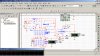
through my PIC i have wired up a 6bit R2R ladder on 5v, i have an opamp fed with 30 volts on +, i would like for the output of my circuit to be able to step from 0-30 vdc, i have gotten this circuit to work ok in multisim but i have not been able to reproduce, is multisim accurate on my circuit operation? am i using proper circuit for this? ect...

the amp i actually used was LT1363
my value for R is 10k (20k=2R)
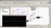
i realize the steps are non linear in sim, since the switching sequence viewed was 1,11,111,1111,11111,111111,

essentially i want the output at 6x input
 

Attachments

  • circuit1.jpg
    circuit1.jpg
    189.9 KB · Views: 341
  • circuit11.jpg
    circuit11.jpg
    169.8 KB · Views: 257
Last edited:
The LT1363 has inputs that cannot go near 0V nor your +30V supply.
Its outputs cannot go as low as 0V nor as high as +30V.

R1 and R2 set the voltage gain at 14, not 6.
 
so that circuit could work?!!
i have tolerance and could range between 5v & 28V on my output if thats enough give.
and taking r2 down to 40-50K is no problem either, but when i ran to troubles i started adjusting R2 and that was the value that worked on sim, i will keep an eye on that so ensure its accurate,
but i am confused i thought i picked out the amp properly, as negative-pin will not be going past 5v,
and positive pin = 30v*1/5 =6v
i though i specked an amp with a 36v max Vcc.
30v supply only provides 10ma
could you perhaps point out a digikey amp that would suit, or elaborate on the specs i failed on?
 
If you accept an output that goes from +5V to +28V then you must use a dual-polarity supply for the amplifier so when the signal source input is +0.83V then the negative supply to the amplifier is about -3V or more.

We do not know what load the amplifier will have, so we cannot calculate its maximum output voltage.
 
we will be using a pull down resistor for the load if necessary, since i am using this to drive a GT60N321 which i found, and i have noticed that a applied voltage stays on the gate until it is drained.
also i can be a little more flexible on the min output value if that would eliminate dual supply,
I have also done rough calculation ( r2r ladder = 6bits & 5 Vmax, 6bit = 63 steps, 5v/63= 0.08v/step)
 
I do not know why you have an opamp driving the gate of an IGBT sometimes, but at other times NOTHING is driving the gate that is floating (therefore the applied voltage stays on the gate). A pull-down resistor at the output of the opamp might overload it and might not make the voltage low enough to completely turn off the IGBT.

I do not know why you are feeding the gate of the IGBT different voltages since it is usually just an on-off switch. Is its emitter connected to 0V? If it is then your opamp output voltage of about +28V exceeds the maximum allowed gate-emitter voltage of 25V.
 
the floating gate was just a test, as i had it hooked to a variable power supply, i am using transistor as a motor driver,
and on a bench test found that with 12v @ collector, emitter would give full 12v out with gate at 30v, and would output 6v when gate was at 15v. that is also when i learned of my minimal current requiremts, as any voltage applied would hold at the gate, i built the r2r ladder so pic would create analog outputs but failed to realize that in r2r demo circuit they used 5v throughout, i built multisim hoping that a few adjustments could save circuit,but do not understand how to math opamps when feedback is involved.

maybe there is a better way to get x6 volts from my r2r ladder?
 
An IGBT has a high gate-emitter capacitance and no input current so of course its gate holds a voltage charge without anything draining it away.

The speed of a DC motor is usually adjusted with pulse-width-modulation, not the DC voltage. A low DC voltage to a DC motor results in low torque so it might not start running.

Your simple circuit has no negative feedback so the motor speed is determined by its load, and its output voltage changes when the temperature of the transistor changes.
 
that first thing i knew those existed, gate emitter capacitance, did not know what it was called till now, but i was only trained with basics for transistors, i find it hard still to ID with data sheets, and there are only few values which i know to look for, usually max power out!, which is why i bench them every time, originally i was testing with pwm, more specifically square (k)hz waves, but then i found the dc flow works better,.

but by what you are saying am i understanding that i will create myself a heat problem from improper saturation?

i would rather use this since the motors are all 6v, but then PIC can do 12v bursts, i have put in V-divider to analog input so PIC can monitor volts, and has control of the 30v driver, and also temperature monitor on transistor, i fear pwm will not give me an accurate reading at gate, and motors would throw off emitter voltages,no? also if i am to drive motors with pwm i would prefer to do it at each independent bridge.

so when you are asking about a load you are referring to what is after the emitter, i thought r3 was the feedback,
after my emitter the transistor will be feeding 4 h-bridges two are 2.5 amp motors, while the other 2 prolly add up to 100ma, all are 6v rated, but all these are another board with another uC as the main computer which feeds data to the 1st PIC which is actually the power circuitry board which is what im working on now.

having said all that , the circuit is my main power supply, it is powered by bench for now, 14v, but will be transitioning to a 11.1 battery, which is why my numbers may have been a bit high, it passes through an 11v feed to 2ESC motor controllers, supplies 5v(7805) for computers, the power line for my 6v motors which we are discussing, and some leds.
 
Please post your COMPLETE and DETAILED schematic of your PIC driving your opamp that is driving the IGBT that drives the motor.

Maybe you have DC motors in a model car, boat, helicopter or airplane and the 11.1V is a Li-Po battery? Their ESC works with PWM for good speed control with lots of torque. If you limit the pulse width to no more than about 50% then the motors get an average of about 6V at full power.
 
I realize it is ruf , hope it is enough thou,
my timer and boost circuit is the one used here in the voltage triple circuit, i used 47uf & 1n4008, and adjusted the 33k and capacitor accordingly.
http://www.talkingelectronics.com/projects/50 - 555 Circuits/50 - 555 Circuits.html#10a


here is the link i used for my R2R ladder:
hyperphysics.phy-astr.gsu.edu/hbase/electronic/dac.html

all those little arrows are where we havn't wired in yet, the one arrow is another V sensor if we need it but have not wired in amp yet since it has yet to give results:
 

Attachments

  • Scan.pdf
    1.4 MB · Views: 195
Your link to Talking Electronics is to an index page with hundreds of circuits, not to the schematic you used.

Your circuit will not need the voltage tripler and amplifier if it used a normal logic-level Mosfet as a PWM common source switch instead of an IGBT as a common collector linear follower.
Also then the Mosfet will switch with normal PWM and stay cool, and the 6A motor will have good speed control and plenty of torque.
 
if you scroll down on that link you will see the index, with the "voltage triple circuit", unfortunately MY circuit is as complete as it is drawn, as it stands if i tie the 30v source to gate i can control pwm with the enable of the voltage multiplier, and will take your advice next time i do a motor driver like that, the reason i fear pwm mostly is that if there is a micro controller crash/stop/reset, i do not want that pwm pin to remain active(high) causing an unwanted burst.

but about the amps,
I have been reading on the op-amps, but i do not get how to calculate when there is feedback, but if i am following your example properly, then amp will output the difference of the two inputs, so if i feed 5v on input and 0v initially on output/ -input, then output will go to 5v, but then 5v*40k/10k(r1,r2) = 1v that feeds back to -input, which then causes a difference of 4v, which would output as 4v, then 4v*40/10 = 0.8v on -input , which then .......ect....

do you see my confusion , can you pls explain where im wrong here?
 
about the amps,
I have been reading on the op-amps, but i do not get how to calculate when there is feedback, but if i am following your example properly, then amp will output the difference of the two inputs, so if i feed 5v on input and 0v initially on output/ -input, then output will go to 5v, but then 5v*40k/10k(r1,r2) = 1v that feeds back to -input, which then causes a difference of 4v, which would output as 4v, then 4v*40/10 = 0.8v on -input , which then .......ect....

do you see my confusion , can you pls explain where im wrong here?
I do not see an opamp in your sideways scribbled schematic.

An opamp must be powered properly. Without negative feedback its voltage gain is 100,000 to 1 million.
Negative feedback is created with 2 resistors as a voltage divider.
Two resistors with the same value produce a non-inverting voltage gain of 2.
A 40k feedback resistor feeding a 10k resistor to ground produces a non-inverting voltage gain of 1+ (40/10)= 5 times. 40k is not a standard value. Use two 20k resistors in series instead.
 
it is at the bottom of scribbles, but not wired in yet, i dont understand thought , if +input ranges from 0-5v, then if we use this negative feedback R2=10k R3=50k, then why wouldn't this output 0-30v, and which opamp would work?
 
opamp.png
I sketched a non-inverting opamp circuit with the resistors you said.
Since its input and output goopamp.png
opamp.png
down to 0V and there is no negative supply voltage then the opamp must be a "rail-to-rail" type.
I have never used a rail-to-rail opamp and I do not know its part number.
 
The datasheet of the LM10 shows that it is a very slow (1khz or less) opamp and an adjustable voltage reference. The reference is disabled by connecting pin 1 to pin 8 on its 8 pins package. The balance pin 5 is used to zero any input offset voltage but you don't need it so do not connect anything to it.
The opamp is almost rail-to-rail when the output current is very low.
 
sweet that sounds like a green light to me! i'ma start rite away, of course it could take a while to do code, but i will post back here when its done, i think you will like this one!

thnx for the the simple rules, much easier than the tutorials!
 
Status
Not open for further replies.

Latest threads

New Articles From Microcontroller Tips

Back
Top