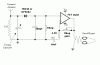
Hi, the attachment contains a diagram of the AM radio circuit we built for a lab
I have a question about Figure 2 Section 3. From what I understand, audiable information is encoded as amplitude of a low frequency signal. This signal "rides" on the broadcasted high frequency signal. Section 3 is a low-pass filter that filters out the high frequency.
Here is the question: for the 0.1uFD capacitor, what will be the optimum resistor value? Why?
My text book has example of low pass filter, but it's a RC circuit in series. I don't know how a parallel RC circuit will behave
Is section 3 and sectoin 4 related? I know that section 4 is just an AC coupler and an inverting amplifier.
Thanks for any suggestion
(PS: I asked this question in another forum but this place seems to be more suitable for simple question)