Continue to Site

Welcome to our site!

Electro Tech is an online community (with over 170,000 members) who enjoy talking about and building electronic circuits, projects and gadgets. To participate you need to register. Registration is free. Click here to register now.

  • Welcome to our site! Electro Tech is an online community (with over 170,000 members) who enjoy talking about and building electronic circuits, projects and gadgets. To participate you need to register. Registration is free. Click here to register now.

am modulator

Status
Not open for further replies.

Dr_Doggy

Well-Known Member
am! modulator

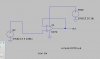
I want to do a am modulator that "codes" my voice to a 40khz signal, I know to use an opamp to mix them, but what is good(simple, stable) way to generate to 40khz for the -pin on opamp,
in the schematic that i cnt find anymore it also used a (FET?) to switch the voice modulation on the + side, but didnt provide a part number, which fet would work for this?,
or what is a generic fet (when the arrow points towards the inside goin in on the base

also to output my signal I am using an h-bridge on my device, will i need to worry about the bridge keepin up to that fast frequency speed?
 
Last edited:
To modulate a signal you need some form of analog multiplication. An op amp can add two signals together but that is not modulation.
 
The ring modulation waveform looks like amplitude modulation.

I am confused. Frequently I have mains hum from an audio circuit and it adds to look like the left graph which looks like a beat note is not formed. But amplitude modulation multiplication looks like the right graph where a beat is clearly visible and will be audible.

Which graph actually shows adding and which graph shows multiplying?
 

Attachments

  • added sinewaves.PNG
    added sinewaves.PNG
    29.9 KB · Views: 194
The circuit you found transmits radio waves on the (WM) AM broadcast band. They are from 540kHz to 1600kHz which is much higher than only 40kHz.
You will not find a tuning capacitor that is 25 times higher capacity than is available. Also the inductor will be pretty big.
Why not use an RC oscillator like a phase-shift or Wien bridge type?

Where will you find an AM radio that tunes 25 times lower than is available?

The antennas will be 25 times longer than an AM radio antenna that is about one km long.
 
lol, snot for a radio, just for my driver, but thats what i want it to do, i tried making oscillators with 555 timers and PICs before, but i had problems, and didn't know what a good clk circuit would be. iv read the word "unstable" a coulpe times.

would this work:
**broken link removed**

and if so how do i multiply it with my microphone sig?
 
Now you show a Wien bridge oscillator. To AM modulate it you amplify the mic signal then modulate (not multiply) its supply voltage.
 
so i would take Rg off of ground and put my signal in on there? or are you saying that i should put my signal on vcc of the opamp?
 
Last edited:
Ask your teacher to explain, look in your text book or look on Google to see how Amplitude Modulation works.
Amplitude Modulation is your signal amplitude changing the amplitude of the carrier frequency.
 
Last edited:
The picture of the ring modulated signal shows double-sideband suppressed carrier AM modulation. A 4-quadrant multiplier can generate that type of modulated signal.
 
Last edited:
to modulate the rail voltage of the op amp would create terrible AM, because it would be 40khz with a modulated clipping level... better to use an MC1496 multiplier, with the 40khz on the X input, and the audio superimposed on a DC level on the Y input.

figure 28 page 9 is an AM modulator ircuit
 

Attachments

  • mc1496.pdf
    310.4 KB · Views: 454
Last edited:
i like the chip, but i found this circuit:
**broken link removed**

would it work?
i dont understand "modulated clipping level", but i do want it to multiply with the signal (smoothly) maybe just stick with the chip eh?
 
that's a mixer circuit, and not really a modulator. by "modulated clipping level" i mean that the op amp would create a square wave output, with the point where the distortion occurs changing with the modulation input.

notice the very bad distortion of the modulated RF
 

Attachments

  • op-amp-am-ckt.jpg
    op-amp-am-ckt.jpg
    22.8 KB · Views: 136
  • op-amp-AM.jpg
    op-amp-AM.jpg
    113.8 KB · Views: 156
Last edited:
hi doggy__

what exactly you want to accomplish? then you can decide which path to take. (for example do you need carrier or not etc).
the transistor circuit you have there can work as AM modulator. it is used in many simple transmitters.
i didn't deal with modulation in a long while but from what i recall doing small signal analysis will show that you
get both sum and product of carrier and signal. if result is expressed in terms of taylor series,
you would get polynomial therms of odd powers. so for this to work well as multiplier, amplitude of signal need to be small (then higher terms of the series become negligible).
i think this is exactly what multiplier chip does too (plus more glue circuitry to massage the signal to levels mentioned in specs).
 
btw. you can do analysis on a computer (you can use free spice from Linear). here is an example done by someone else:
**broken link removed**
 
um well i have a 30v 50w ultrasonic transducer, and i want it to run off my voice, so i need this circuit to ampilify for the output, i also will want it to run pure on the 40khz,

i would also like to do this to modulate the driver(different carrier frequency) for my tesla coil like those guys who have those singing coils... right now it is run from a 2n3055 driver.

i will use the chip if it means best results, also what type circuit should i use to generate that 40khz sin carrier, awesome if there is a simple chip for that too! also i do this all on breadboards with long legs and iv heard capacitance can be thrown off, so something to get me round that would be bonus too!
 
Status
Not open for further replies.

Latest threads

New Articles From Microcontroller Tips

Back
Top