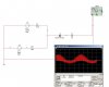
I'm designing a simple A.M. radio for class. I have an oscillator and audio input. How do I mix these together to get Amplitude Modulation? I attached my best guess design but it looks like only the top half of an AM wave. Please comment.
Also, does the oscillator and signal have to be at the same voltage amplitude?
With the diode design, does the combination of the osc. and signal have to be greater than 0.7V because of the diode? B/C the audio signal I have outputs at around 300mV
Thanks
Also, does the oscillator and signal have to be at the same voltage amplitude?
With the diode design, does the combination of the osc. and signal have to be greater than 0.7V because of the diode? B/C the audio signal I have outputs at around 300mV
Thanks