Continue to Site

Welcome to our site!

Electro Tech is an online community (with over 170,000 members) who enjoy talking about and building electronic circuits, projects and gadgets. To participate you need to register. Registration is free. Click here to register now.

  • Welcome to our site! Electro Tech is an online community (with over 170,000 members) who enjoy talking about and building electronic circuits, projects and gadgets. To participate you need to register. Registration is free. Click here to register now.

Am i wrong here

Status
Not open for further replies.

Megamox

New Member
A friend asked me to help him answer a question for his past paper revision notes, and apparantly i got it wrong. Now i look silly!. The question was:

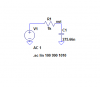
What value of capacitor must be added in series with a 1k ohm resistor, and signal source (1v peak @ 1khz) to complete the potential divider and reduce the peak voltage to half.

It should be 92nf right???

His Teacher marked it wrong and said the answer was 159uf - with a little note on the side "Reactance of 90nf does NOT equal 1k ohm at 1khz".

Who's right??

Megamox
 
You're both wrong. The answer is 276nF.

Vo/Vin=(1/RC)/(jw+1/RC), where w=radian frequency=2*pi*F

|Vo/Vin|=(1/RC)/sqrt(w^2+(1/RC)^2)=0.5, by problem definition

F=1000, R=1000

solving for C,

C=sqrt(3)/(w*R)

C=275.66nF

The teacher's solution (probably 159nF, not uF) does indeed give Xc=1k@1kHz, but due to the associated 45 degree phase shift, the resulting amplitude is 0.707V.

Tell your friend to take this back to the teacher. :D
 
I know why i got 92nf now, i was using the input as 1v RMS. When you feed in 1V RMS you get 0.5v RMS out, with a 92nf cap and 1kohm, @ 1khz :D
 
Megamox said:
I know why i got 92nf now, i was using the input as 1v RMS. When you feed in 1V RMS you get 0.5v RMS out, with a 92nf cap and 1kohm, @ 1khz :D

RMS, peak, whatever - it doesn't matter, so long as you are consistent. The answer is still 276nF. How did you come up with 92nF?
 
I made the magnitude of the impedance = 2k and solved for the capacitive reactance. Then rearranged to get C.

My simulator gives out 0.5V RMS, with an input 1v RMS?
 
Megamox said:
I made the magnitude of the impedance = 2k and solved for the capacitive reactance. Then rearranged to get C.

My simulator gives out 0.5V RMS, with an input 1v RMS?

2k :?: :?: :?: Why 2k :?: :?: :?:
Anyhow, the impedance of 92nF at 1kHz is 1.73k.

And your simulator is either wrong, or you are using it wrong, or misinterpreting it. Can you post the schematic and the waveform (or Bode plot)?

Below is a sim from SwitcherCAD.
 

Attachments

  • rc_divider_waves.png
    rc_divider_waves.png
    17.8 KB · Views: 463
  • rc_divider_sch.png
    rc_divider_sch.png
    5 KB · Views: 471
I agree with Megamox. If you assume the output voltage is across the resistor then.

Vo/Vi = R/(R + 1/SC) = 0.5 Let SC = jwC

Vo/Vi = R/(R - j/wC) = 0.5

Thus wRC/(wRC -j) = 0.5

Take the modulus wRC/sqrt{(wRC)^2 + 1} = 0.5

Square both sides and rearrange 4(wRC)^2 = (wRC)^2 + 1

3(wRC)^2 = 1 gives C = 1/{sqrt(3) wR}

C = 92 nF

Edit: After posting this, I noticed Ron's latest post. He has the output across the capacitor. Whereas, I assumed it was across the resistor. So I'll re-do the maths to see if it agrees with Ron's simulation.
If R = 1000 ohm, w = 2 pi * 1000
 
See my edit.

I would appear that the difference is whther you take the output across the resistor or the cap. I'll do the maths and see if I get the same answer as Ron if the output is across the cap.
 
I transposed the R and C and re-did the maths. This way, the answer is 275 nF as Ron said.

So we are all right! (except your teacher)

I had a feeling that the Xc of the cap would not = 1 k for the output to be half.

The relationship between the supply voltage and the voltages across the R and the C is not linear. They are related by Pythagorus (I'm not sure about the spelling)
 
Len, you're right. Megamox, please accept my apologies. As Len said, I assumed the lowpass configuration. I think the original wording implied the highpass config, which I didn't even consider. I guess I was only half wrong. :oops:
Anyhow, the teacher needs some re-education.
 
ljcox said:
They are related by Pythagorus (I'm not sure about the spelling)
Pretty amazing, when you consider Pythagoras had never heard of a capacitor (or even a condenser, or a Leyden jar, for that matter). :)
 
Its all Greek to me! You were not actually wrong Ron, I just assumed the output was across the resistor as it seemed to be easier in the maths.

Actually it is slightly easier the other way.
 
ljcox said:
Its all Greek to me! You were not actually wrong Ron, I just assumed the output was across the resistor as it seemed to be easier in the maths.

Actually it is slightly easier the other way.
Yeah, I know. I just felt bad for chiding Megamox while not considering that there were two solutions.
God, I hope Megamox has a way to get this back to the teacher. We have enough guys giving bad advice in this forum. We don't need teachers creating more of them! :roll:
 
The teacher probably meant that the capacitor with a reactance equal to the resistor will produce a half-power output from across the capacitor.
The voltage is at 0.707, therefore the output is 3dB down which is half-power.
 
Ron, no need to apologise! :D

Yeah the wording doesnt really specify the configuration, and i automatically assumed the high pass. So both answers are valid :D

Megamox
 
Len, I see you've been on this forum for 2 years. You need an avatar so we can more easily spot your posts, and also to see what sort of foolish picture you select for it. :lol:
 
audioguru said:
The teacher probably meant that the capacitor with a reactance equal to the resistor will produce a half-power output from across the capacitor.
The voltage is at 0.707, therefore the output is 3dB down which is half-power.
Audioguru, I agree - but that's apparently not what he said (unless he was misquoted, which is entirely possible, since we're getting it third hand).
 
Status
Not open for further replies.

Latest threads

New Articles From Microcontroller Tips

Back
Top