Continue to Site

Welcome to our site!

Electro Tech is an online community (with over 170,000 members) who enjoy talking about and building electronic circuits, projects and gadgets. To participate you need to register. Registration is free. Click here to register now.

  • Welcome to our site! Electro Tech is an online community (with over 170,000 members) who enjoy talking about and building electronic circuits, projects and gadgets. To participate you need to register. Registration is free. Click here to register now.

Am I USING PIC UART CORRECTLY??

Status
Not open for further replies.

cyprio7

New Member
hello everyone.

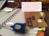
i have written a very simple program for PIC16f628, which sends the word "hello" over the TX UART pin, to the RX pin of a DLP(device which recieves rs232 and sends it out via usb to a different device). The DLP is connected to my pc via USB. I have created a virtual comport COM6 for the DLP, so that the PIC can communicate with pc in a serial fashion, but through the interface of a USB connection instead of an old fashioned 9pin serial way. hope this makes sense.

anyway, set up the PIC to transmit the data as soon as it starts up once, then to transmit it whenever rb4 is set high by pressing a button etc.

i have made a connection to the DLP that the PIC is connected to via hyperterminal. i am using baudrate of 9600, 1stop bit, no parity.

i am not seeing my message come up onto the screen in hyperterminal. i have looked over my code a thousand times and i cant find the problem. could someone please look at my code, to confirm to me if the PIC is actually properly outputting the data through its UART TX pin. this way i can find out if the problem is with my programming of the PIC or with the DLP.

i am using hyperterminal private edition, on windows vista, because for some reason they decided not to include hyperterminal.

please help because iv exhaused myself trying to fix this by i cant find the problem and its starting to make me depressed.

i have attatched the code

thank you
 

Attachments

  • program.txt
    2.4 KB · Views: 226
The 16F628 data sheet states that RX and TX should be set to input in order to use the UART. Also, are you using a max232, it may be that the UART to USB chip takes TTL level data or you may need a level converter.

One other thing, your goto message will cause a crash.

Mike.
 
hi,
Runs OK, on OS Pic sim, prints 'hello' on UART window, then stops.

As Mike says, check the level shifters, also make sure you are using pin #8 of the PIC.


Mikes...One other thing, your goto message will cause a crash. make it a Call and it controls OK with B4.
 
Last edited:
hey thanks for your reply. but, where does it say that the rx, AND tx pin should be input?? i couldnt see that? i thought that tx must be output and rx must be input.

the pics uart uses NRZ so that is not TTL.

i have attatched the datasheet for the DLP. i am using it in rs232 serial mode. my friend said that pins such as RTS ,CTS, DTR, DSR etc do not have to be used (as seen on page 18 of datasheet in table), he said only the tx and rx pins, pin 39 and 40 must be used. if so why have the other pins, surely they must be there for a reason?
 
here is the datasheet for the DLP i am using.
 

Attachments

  • FT2232C datasheet.pdf
    958.5 KB · Views: 341
Before you start pulling your hair, check your cable.

If you do not have oscilloscope, as a simple test, you can write a little program to periodically send a character to UART and check with AC meter which line is toggling.
 
There is a lot of places to make a mistake with this type of connection and PIC is just one of them. Make sure your hyperterm and USB to serial are set up correctly. In order to do this short tx and rx pins of the USB to serial chip on the TTL side, open the hyperterm and type something on the keyboard. If everything is set up correctly you should get characters that you type echoed back on the screen. If you're not getting echo check flow control of your virtual serial (should be set to none) and VCCIOx pins on the chip (they should receive power). When you get this part done you may start troubleshooting the PIC.
 
On page 78, step 1 of the description for how to transmit is,
TRISB<1> and TRISB<2> should both be set to
‘1’ to configure the RB1/RX/DT and RB2/TX/CK
pins as inputs. Output drive, when required, is
controlled by the peripheral circuitry.

Looking at the data sheet you posted, the levels are RS232 levels and so a max232 chip is required between the chip and the pic. Do you have one? An alternative method is presented here. Note that the loopback test suggested above will work correctly without the chip.

Mike.
 
your code work properly here (with goto message change to call message), but i doubt of the reliability of ANY internal OSC. See here, 1 out 5 don't work with internal and just send garbage while i don't see any problem with a real 4Mhz crystal.
 
I have never had a problem sending serial data with the internal oscillator. My current project has serial at 115k and uses the internal oscillator without problem. I would guess that in order to get the last bit wrong your timing would have to be out by ½ a bit or 5%. The internal oscillator is accurate to 1%. Are you maybe thinking of AVRs where the error can be 5%?

Mike.
 
I may agree with some newer PIC wich have internal calibration... and 1% marked on... but this poor ol' 628? maybe 628A is better... look the regular 16F628 datasheet
https://www.electro-tech-online.com/custompdfs/2007/12/40300C.pdf
pdf page 138, parameter 4 :eek: unless i don't interpret it correctly... it's way more than 1%

And bear in mind it's an RC osc.. so it WILL shift at least with temperature variations. Not fan of it for reliable serial comm...
 
Last edited:
Mister E,

You are correct, the error with the non A version is substantially higher and could cause serial communication problems - I have only used the later version and, therefore, did not appreciate this fact. However, this is not the OPs problem as if it was he would be getting garbled data rather than no data. I think his problem is hardware - probably no level shifter.

Mike.
 
mister_e,

I was referring to experiences with the newer devices with INTOSC 1% tolerance too.

If your recommendation is based on your experiences with "old" devices then your experience and recommendation are both a bit out-of-date.
 
Yup, i'm not totally close to the idea, i should try it one day. But now, i still use the old 'thinking' even with newer PIC... i'm afraid... there's people like that ;)
 
mister_e said:
I may agree with some newer PIC wich have internal calibration... and 1% marked on... but this poor ol' 628?

I've used 628's extensively at 9600 baud with the internal oscillator, and have never seen a problem at all.
 
thanks for all your replies.

iv decided to not use the DLP because it is causing too much headache. not to mention it is expensive.

instead i have opted to use a usb to serial converter lead from maplin and write serial data to it by again creating a virtual com port. the link below shows the usb to serial converter from maplin i am using

**broken link removed**


i have set up hyper terminal to have

1start bit
1stop bit
9600 baud
none flow control


i connect my usb2serial lead to the usb of the laptop, a virtual com is created, and i am able to connect to it in hyper terminal. now here is the problem..

i was told that to test that hyper terminal and the lead is ok, short the tx and rx pins of the serial side of the serial-usb cable(pin 2&3).

then type something into the hyperterminal window. this means what u type is sent from the pc, from the USB end of the usb-serial cable, to the serial end and appears at the rx pin of the serial end. because rx and tx are shorted, whatever appears on rx appears on tx, therefore, the same signal is sent back along the USB-serial cable, and recieved at hypeterminal. it is looped or "echoed" back, and the characters appear on the screen. this works. when i un-short these pins and i type on the screen, no characters come up, which is normal, because hyperterm isnt recieving any data, right?


now, i connected the serial end of the USB-serial cable(pins rx and tx), to a 9pin serial d-sub to its corresponding rx and tx pins. i am ONLY using the rx and tx pins because i am not using any hardware flow control.

when i connect them, iv noticed when i type on the hyperterminal, the characters come up!! why is this? i thought ok, maybe my soldering is bad and i have shorted these pins, which is why it is being echoed back, i checked, but nothing. i have not shorted them. how comes what i type into the keyboard is being echoed back and displayed on the screen? note this is only when i plug in the 9pin serial d-sub connecter to the serial end of the serial-usb cable. does any body know what it could be??

i wil try and include a picture to explain this better
 
i have attatched a picture, to try and explain what i mean. thanks
 

Attachments

  • explanation.jpg
    explanation.jpg
    519 KB · Views: 194
thanks for ur help but it didnt work. i tried a way of finding problem, what i did was..

as u can see, the serial d-sub connector has 2sides. one side with female holes, and the other sides with pins sticking out which have solderd the wire to which lead to my circuit.

when i test using the multimeter with the beep thing, the tx and rx pins on the d sub serial connecter are not shorted.

what i did was, i put a wire in the TX hole of the d-sub, and the other end of the wire i tied to +5V. this now means +5V being supplied to TX pin of female hole of serial d-sub connector.

i then took out multimeter, and put one strobe on ground, and the other strobe on the TX pin of the serial d-sub connector, but on the OTHER side, if u get what i mean.. on the side where i solderd a wire onto it which leads ot my circuit. the multimeter read 5V. that is correct i hear u say. indeed it is.

i then put the positive strobe of the multimetre on the RX pin of the serial d-sub connector (on the side where i have soldered wires onto not the side with the female holes).. it should be zero volts right? because on the other side i am ONLY supplying the TX pin with 5V. well, it was not zero, it was 3.56V.

this implies to me that something is wrong? refer to my picture i posted if u have trouble visualising this. could it be that when i solderd the tx and rx wires into the serial d-sub connector, that too much solder leaked down into the little "cup" and into the connector, forming some kind of connection between the pins. however if there was a connection then they should both be the same voltage right?

does anybody know what the problem may be? thanks
 
Status
Not open for further replies.

Latest threads

New Articles From Microcontroller Tips

Back
Top