Continue to Site

Welcome to our site!

Electro Tech is an online community (with over 170,000 members) who enjoy talking about and building electronic circuits, projects and gadgets. To participate you need to register. Registration is free. Click here to register now.

  • Welcome to our site! Electro Tech is an online community (with over 170,000 members) who enjoy talking about and building electronic circuits, projects and gadgets. To participate you need to register. Registration is free. Click here to register now.

Allegro A3245 Hall Sensor Problem

Status
Not open for further replies.

kentken

New Member
I am building a ignition system for a model engine using the Allegro A3245 sensor.
I had a problem with the sensor, after some time the sensor stops working right, it stays in conduction, and wont release. I am using a 12v supply and a car ignition coil.

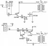
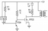
Attached in the sch of the designs, the bottom one is found online for model engines.

Are the resistor valuses off?? Is there something else off in the design??

Thank you
Kent Kenison
 

Attachments

  • ignsys.jpg
    ignsys.jpg
    50.6 KB · Views: 676
In your circuit, the output of the Hall effect device is connected to 12-.5=11.5 volts. There is a current limit in the hall device but I don't know what it is. If the limit is 1/2 amp, the power disapated in the hall device is over 5 watts and is destroying it in short order. You need a resistor in series with Q2 base.
 
You should also include a freewheeling diode in your circuit to protect the power transistor from the transient which occurs when your circuit switches the transistor off. Otherwise, it may not last long either. (The IRF520 MOSFET has such a diode built-in.)
JB
 
I did try a resistor between the hall output and the transistor, it would do the same thing.
Any sugestions on the resistor sizes that would be the best, I am not sure what the current should be, the only rating I could find wa 30-60mA, but I don't know.

Thank you
 
12V power is fine. Output current is limited to as little as 30mA (datasheet says 30..60). This means you should not have more than some 20mA in normal operation or sensor might protect itself. Assuming battery voltage up to 16V and 20mA current, you would need load such as 820 Ohm or more.
On first circuit all you got is PN junction with Vbe of only 0.7V which is really bad. The second circuit looks better but again, change that R3 to at least some 680-750 Ohm. Also, jbeng is right about diode.
 
Thank you,
I will try that, and hopefully will have success.
I will let you know how it works.

Thank you
Kent
 
Well, I finally got a chance to rebuild this ignition.
I assembled the bottom one in the sch. Had it all build and went to test it, and I had voltage at the coil conection all the time.

I assumbed that R3 was to blame, and found that the current was OK. Tried and tried to find the problem, currents etc. I disconected the TIP42 base and pulled it up to power, and it is FRIED, and of course I don't have another.

I have: TIP29A, IRF720, IRF520

I've been looking around and had no luck finding another large PNP tranistor.

So my question is, what would it take to make one of these work like in the first drawing? values suggestions? etc.

FYI: I am building this for a friend and he wants to run his motor he just built, so he keeps asking me.
After a day of building and working with PLC panels all day at school....
I need some sleep. :?

Thanks again
Kent Kenison
 
The problem with the circuit is that there was no snubber on the coil, so the backswing when the transistor turned off exceeded the collector voltage rating and fried the power transistor.

This circuit uses the parts you have and has a snubber. If you have an oscilloscope, you can adjust R3 for about 50 volts peak, otherwise leave it at 100 ohms.
 

Attachments

  • ignition_switch.png
    ignition_switch.png
    16.2 KB · Views: 549
Thank you for the design, I should be able to build it tomorrow, I hope.
I will let you know how it works.

Thanks again,
Kent Kenison
 
Status
Not open for further replies.

Latest threads

Back
Top