Continue to Site

Welcome to our site!

Electro Tech is an online community (with over 170,000 members) who enjoy talking about and building electronic circuits, projects and gadgets. To participate you need to register. Registration is free. Click here to register now.

  • Welcome to our site! Electro Tech is an online community (with over 170,000 members) who enjoy talking about and building electronic circuits, projects and gadgets. To participate you need to register. Registration is free. Click here to register now.

Air quality and co detector

Status
Not open for further replies.

Ramees raja

New Member
Hi
i want to design a microcontroller based programable air quality and co detector device.in this project their is 2 sensors used air quality sensor and co sensor
there is an alarm and lcd in the output
i/p section_reset ckt,oscillation ckt,sensor1,sensor2
o/p section_lcd,alarm,relay ckt,
and the mc is 16f877a
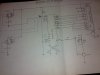
please help me to draw the ckt dgm
 
Unless we know which sensors, lcd unit(s), alarm etc you are using we can't help with a circuit diagram.
The term 'air quality' could mean several things. What do you understand it to mean?
 
I have two sensors,one is carbon monoxide sensor and the other is semiconductor gas sensor.
16*2 lcd is used for displying amt of co and other gases.if sensors sense some amt of co which is greater than fair amt then alarm is turned on
please help it is urgent
 
Last edited:
We will need to know the specifications of the sensors and lcd unit. What are their type numbers? Can you post links to their datasheets?
What alarm type?
Is the 'oscillation' circuit just the clock oscillator for the micro, or something else?
What is the relay circuit for?
What power supply will you use?
 
Oscillator ckt is just for clock pulse,i have no idea about relay,i only know the above.i have only the block dgm,i have know the idea but not the specifications,
please help
 
i only know the above.i have only the block dgm,i have know the idea but not the specifications,
Then we can't design a circuit diagram. The best we can do is a block diagram of the whole system.
 
OK, then based on all of the information you provided here is what you do. You have two sensors that will have outputs. You condition those outputs using signal conditioning, unless of course for the uC inputs signal conditioning is not needed, then you omit signal conditioning for one or both channels. The sensor outputs with or without signal conditioning get passed to the micro controller A/D inputs as a linear voltage proportional to air quality and atmosphere CO content. You program the uC so when preset limits are exceeded (for the analog inputs). You can have an alarm for each or an alarm for both. Digital output pins of the uC toggle low to high and trigger alarm(s) based on analog input signals.

Without data sheets for the sensors and without knowing the uC analog input range or A/D conversion bits, that is as good as it gets.

Ron
 
Sensors
1,co sensor-code,mq7
2,air quality control sensor-code,mq135
lcd
hitachi HD 44780
UC
16F877A ANALOG IP RANGE 8
POWER SUPPLY 5VDC
THE AMT OF GASES AND CO IS DISPLAYED IN LCD
IF SOME AMT OF CO IS DETECT THEN ALARM IS ON
JUST A SIMPLF ALARM
PLEASE HELP GUYS
 

Attachments

  • MQ-135.pdf
    145 KB · Views: 289
  • HD44780.pdf
    389.9 KB · Views: 153
  • CO.pdf
    41 KB · Views: 205
This is a good link to a more informative data sheet from SparkFun Electronics for the MQ-7 sensor. The sensor output is an analog resistance so you add a load resistor, they explain that. Personally I would use a 5KΩ fixed resistor in series with a 50 KΩ pot to allow for calibration.

Note Figure 5 in my link. Best results using sensors of this type are obtained using a PWM signal to the heater element. Additionally they suggest a 48 hour "burn in" for the heater element.

While sensors of this type do work, they are not very accurate unless calibrated using calibrated gas samples.

This is the uC you have chosen. It gives you 8 each 10 bit A/D channels. It also gives you two analog signal comparator channels. So you program your uC for whatever you want it to do.

This sounds like a homework or schoolwork assignment. While people will help you and give you pointers, they will not do your schoolwork.

Ron
 
The first step I'd suggest is draw a block diagram showing the power supply and all the input and output devices and their links to the micro. Then you can concentrate on one section at a time and flesh out the details of pin connections for each device.
 
The first part of a circuit diagram is included in the data sheet? What part of that do you not understand? Next is a suggested PWM circuit to power the heater as covered in the link. Finally a load resistor across the output of the sensor to give you a voltage drop to send to the uC. The suggested PWM is 60 seconds of 5 volts and 90 seconds of about 1.4 volts for the heater in the sensor. What part of this do you not understand? I suggest you ask your teacher exactly what is expected?

If you just want alarm functions you don't even need a uC, this could be done using simple comparator circuits.

I told you to place a 5K resistor in series with a 50K pot across the sensor output. That will give you a voltage out proportional to what the sensor detects.

Ron
 
Hai
thanks for all valuable informations.
Please help me to draw a ckt dgm.
In my project their is a relay unit in output.i have no idea abt that,please help me to draw a relay unit ckt .
the block dgm and details attached
thank yu
 

Attachments

  • UC%20BASED%20AIR%20QUALITY%20&%20CO2%20DETECTION.pdf
    108.8 KB · Views: 854
OK, the micro controller output(s) are very low current. They can't sink or source large amounts of current to directly drive a relay coil. Attached is a very basic example of one of the many circuits that could be used. The circuit uses a simple NPN transistor to drive a relay coil. It is only an alarm interface example.

Also, the document you attached seems incomplete and explains nothing? I have no clue why it is labeled "confidential" either.

Ron
 

Attachments

  • Image1.gif
    Image1.gif
    11.7 KB · Views: 127
Thanks ron
now,i have doubt in coding
will yu please tell me what are the stages in coding for this and a link to fullfill my coding
 
I suggest you look for online tutorials in programming micros, in particular PIC micros. Do you intend coding in assembler or a higher language such as C?
 
I very much agree with Alec. Additionally my programmer skills are lacking. :(

These forums do have a very good micro controller section with some very, very good programming types.

Ron
 
Why do you want to connect the buzzer to the relay? If the relay and buzzer are to be switched on at the same time and the buzzer is rated at Vcc then the buzzer '+' terminal can be connected to Vcc and the buzzer '-' terminal can be connected to the collector of Q1. BTW you don't show the relay contacts. What would they be used for?
 
Status
Not open for further replies.

Latest threads

New Articles From Microcontroller Tips

Back
Top