Hi markelectro,
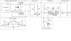
Ok, there you are the most simple circuit i can suggest, keeping in mind its reliability.
In contrast of what it said previously, i took the freedom to modify the circuit of the calendar to simplify the electronic part.
Pulsing the inductor by the negative, the microcontroller can exciting this by a simple NPN (BC337).
The diode D1 is very important to short the high voltage produced when the swich turns off.
All other pulse switches existing must have one diode also. If not, the high voltage, can produce interferences on our PIC.
Ok, about software i will try to have some time to think a little time to design the flowcharts in first place.
In a first sight we need the follow routines / functions:
timer_interrupt: to handle timings for key, led and pulses IN/OUT.
key_handle: to handle the states of the key like CLICK, LONG KEY DOWN, etc.
led_handle: to handle led states like blink when key pressed, flash n times, etc.
config: to set day/month from the key states and save this parameters in the internal eeprom.
For all this i suggest the use of machine states that is the most reliability way to maintain the things under control.
Don't be afraid, when you see, you find out that is very easy and your programming style never more it will be the same.
To acomplish your request, in the next post i will explain how this hardware works.
Regards,
jolino
Attachments
Last edited:
