shockedmonkey
New Member
Can I please get advice on the following 6 questions. I'm a lightweight - any advice is sincerely appreciated.
I want to put 12-VDC LEDs along my basement steps. I wired an outlet under my steps - wired as a 3-way w/ wall switches at top+bottom of stairs.
Q1: My outlet tester shows a very faint bit of amperage when my 3-way switches are off - the guy at Lowes says this is OK/normal? But is it OK for LEDs?
I bought a laptop-type AC/DC converter - 12VDC delivering 2.5Amps,
and some Eurostrips + Jumpers (Radio Shack calls these European Connectors).
I have 2 LEDs to try out. My plan is for 28 LEDs total (3 to 5 LED bulbs per LED-pkg). These are the step LEDs one sees all over the internet (3 or 5 LEDs in package, for motorcycles/cars).
3-LED light is 26-Milliamps, 5-LED is say 50 (or max 80-Milliamps).
So, my total amperage is between .7 and 2.2 Amps.
The LEDs don't seem to need any driver - people put these on motorcycles w/ no mention of an LED-driver needed. (Maybe no driver just shortens LED-life).
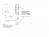
Q2: Will things work per my attached diagram? That simple?
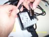
Q3: Attached picture shows the AC/DC converter's device-end plug. I'll cut off this plug - but how do I tell which of 2 wires is the hot?
i.e. Does checking voltage/continuity work just 1 way or is it ambiguous if I have a fancy tester that may 'correct' automatically if I cross my 2 tester-sticks > Told you I'm clueless!
Q4: I assume my ground-wire ends within the AC/DC converter box, so I'll just skip any grounding?
Q5: I'll use 14-2 (low voltage) wire as needed?
Q6: I'll put Eurostrips, etc into a junction box. Am I within Code for this whole contraption?
Thank you for advice/help.
I want to put 12-VDC LEDs along my basement steps. I wired an outlet under my steps - wired as a 3-way w/ wall switches at top+bottom of stairs.
Q1: My outlet tester shows a very faint bit of amperage when my 3-way switches are off - the guy at Lowes says this is OK/normal? But is it OK for LEDs?
I bought a laptop-type AC/DC converter - 12VDC delivering 2.5Amps,
and some Eurostrips + Jumpers (Radio Shack calls these European Connectors).
I have 2 LEDs to try out. My plan is for 28 LEDs total (3 to 5 LED bulbs per LED-pkg). These are the step LEDs one sees all over the internet (3 or 5 LEDs in package, for motorcycles/cars).
3-LED light is 26-Milliamps, 5-LED is say 50 (or max 80-Milliamps).
So, my total amperage is between .7 and 2.2 Amps.
The LEDs don't seem to need any driver - people put these on motorcycles w/ no mention of an LED-driver needed. (Maybe no driver just shortens LED-life).
Q2: Will things work per my attached diagram? That simple?
Q3: Attached picture shows the AC/DC converter's device-end plug. I'll cut off this plug - but how do I tell which of 2 wires is the hot?
i.e. Does checking voltage/continuity work just 1 way or is it ambiguous if I have a fancy tester that may 'correct' automatically if I cross my 2 tester-sticks > Told you I'm clueless!
Q4: I assume my ground-wire ends within the AC/DC converter box, so I'll just skip any grounding?
Q5: I'll use 14-2 (low voltage) wire as needed?
Q6: I'll put Eurostrips, etc into a junction box. Am I within Code for this whole contraption?
Thank you for advice/help.
")
