Continue to Site

Welcome to our site!

Electro Tech is an online community (with over 170,000 members) who enjoy talking about and building electronic circuits, projects and gadgets. To participate you need to register. Registration is free. Click here to register now.

  • Welcome to our site! Electro Tech is an online community (with over 170,000 members) who enjoy talking about and building electronic circuits, projects and gadgets. To participate you need to register. Registration is free. Click here to register now.

advance diode question

Status
Not open for further replies.

07potatoes36

New Member
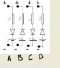
in the attachment there are four circuit diagram (A,B,C,D)
questions:
1). What are the condition for the diode to conduct in circuit A,circuit B,circuit C , circuit D?
example : in A the VRA must be bigger than VA for the diode to conduct.


please help me , i know that diode only allows current to flow in one direction.. but the problem is there are resistor and another voltage source connected here ... please help me..
 

Attachments

  • Untitled2.png
    Untitled2.png
    34.2 KB · Views: 321
Hello,

What are those big plus and minus signs, is that another voltage source being connected?

What model of the diode are you using?
 
yes its another source..its a semiconductor diode perhaps and i have no idea what model it is... i just copy the question from the whiteboard...i ask the lecturer but he ask me to find the topic in youtube .. and here is the link... https://www.youtube.com/watch?v=qEg3DrBe-3U (please watch at 16:00)
the cirsuit diagram is exactly the same ...but i dont understand sigh...
 
Hello again,


Ok for these problems he assumes about zero volts drop for the diode, so it's either a short or an open depending on the terminal voltages.

Lets look at A first with a battery voltage equal to 1 volt...
When the diode is not conducting it is open, so any voltage applied to the plus + input on top appears at the anode of the diode. That's because the resistor cant drop any voltage unless there is current flowing through it. So if we apply 0.5 volt for example we see 0.5 volts at the anode of the diode too. Now we look at the cathode. Since the cathode connects to Va and we made Va equal to 1 volt, that means the cathode is at +1v. So the anode is at +0.5v and the cathode is at +1v. That means the diode is reverse biased so it does not conduct. That means no current flow through the first resistor.

Now lets increase the terminal voltage to 1.1 volts. Now we follow it down through the resistor and we see 1.1 volts at the diode anode. Since 1.1 volts is greater than the voltage at the cathode (1v) that means the diode is actually conducting, and since we assume 0v for these problems that means the top (anode) is also +1 volts. So we started with 1.1 volts for the purpose of deciding if the diode was turned on or not, and we ended up with +1 volt at the anode. So with 1.1 volts applied at the terminals the first diode conducts and since the anode is at +1v that means we have 0.1 volts across the resistor. If the resistor was 1k, then we would see a current:
I=0.1/1000=100 micro amps.

So you first assume the diode is open and then calculate the voltage at the top of the diode. If the difference between the top of the diode and the bottom of the diode is greater than zero and the anode voltage is greater than the cathode voltage, then the diode is really 'on' and the voltage at the top is the same voltage as the bottom, so you can calculate the current through the resistor by subtraction.

See how this works now? No problem if you have more questions.
 
thank you sooo much sir.. correct me if i am wrong, your saying that the voltage at the anode side of the diode must be larger than the cathode side for diode to conduct am i right?:D..
 
Hello again,

Yes that's right except instead of using the word 'larger' use the word 'higher' or 'more positive', the anode must be more positive than the cathode. So if we had say +1.1 volts at the anode and +1.0 volts at the cathode the diode would 'switch' to the on state.

Note that because he assumes the diode model is the perfect diode switch, when this happens we might then make the voltage at the anode equal to the voltage at the cathode, or the voltage at the cathode equal to the voltage at the anode, depending on which voltage is allowed to change. So we effectively short out the diode and analyze the circuit a second time once we know it is 'on'.

This might seem strange and it is a little bit strange, and that's now how a diode works in real life, but it's a simplified model of the diode where we allow the diode to be a short circuit when it is turned on. This simplifies the analysis. In real life we'd see a voltage drop across the diode of somewhere between 0.5v and 1v or maybe a little higher sometimes, but for these problem we dont have to be concerned about that because the lecturer is using this simplified switching model for the diode.

Note that with this diode model the anode voltage only has to be more positive by a small amount, so even if the anode was +1.001v and the cathode +1.000v, the anode is again more positive so the diode switches to the 'on' state, so we can short it out.
 
Status
Not open for further replies.

New Articles From Microcontroller Tips

Back
Top