Axle Roads
New Member
I need a circuit for an adjustable voltage reducer. My analog switching instrument voltage reducer (limiter) is broken and I would like to build a better one.
Input voltage 12V - 15V
Output voltage 5V - 7V
Max Output current 3Amp (estimated)
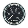
Battery -> IVR -> Load (gages)
I'm just beginning to learn about switched-mode power supply and pulse width modification; LM317, 555. Variation in input voltage will be minimal, so I imagine even a scr might work.
This is the closest circuit I have found so far. I found it on this site. I've looked at data-sheets and prev. posts. I'm having trouble finding something with a high enough amp tolerance. Not sure if I need a transducer. If I could just make a PWM unit to 6 or 7 volts I could maybe tune my gages with a variable resistor or Z-diode. What do you think?
Input voltage 12V - 15V
Output voltage 5V - 7V
Max Output current 3Amp (estimated)
Battery -> IVR -> Load (gages)
I'm just beginning to learn about switched-mode power supply and pulse width modification; LM317, 555. Variation in input voltage will be minimal, so I imagine even a scr might work.
This is the closest circuit I have found so far. I found it on this site. I've looked at data-sheets and prev. posts. I'm having trouble finding something with a high enough amp tolerance. Not sure if I need a transducer. If I could just make a PWM unit to 6 or 7 volts I could maybe tune my gages with a variable resistor or Z-diode. What do you think?
")
